Table of Contents
Advertisement
Quick Links
TOOLS REQUIRED FOR ASSEMBLY
Socket set, Open end wrench set, Cordless
drill with 3/8" socket bit (Magnetic recommended).
BEFORE ASSEMBLY
Read through the assembly instructions to
familiarize yourself with the order in which
the parts are assembled. We suggest that
you clear & vacuum the area where the bench
is to be assembled. It is important that the
bench is assembled in the same sequence
as instructed.
HARDWARE
All assembly hardware is provided.
LEVELER KIT OPTION
**SKIP THIS STEP IF YOU HAVE NOT PURCHASED THE LEVELER OPTION**
Thread 1 thin nut onto the leveler.
Place leveler into floor-mount hole at
the base of the leg or the base of the insert
if its an adjustable height bench. Thread the top
nut onto the leveler.
Loosen & tighten nuts to adjust the height
of your work bench.
MOBILE CASTER KIT OPTION
**SKIP THIS STEP IF YOU HAVE NOT PURCHASED THE CASTER OPTION**
Attach the single bolt casters to the bottom of the legs or the base of the insert if
its an adjustable height bench..
NOTE: TWO TYPES OF CASTERS ARE PROVIDED (SWIVEL AND FIXED) BE SURE TO USE
TWO OF THE SAME TYPE AT EACH END OF THE BENCH (TWO SWIVEL CASTERS ON
THE RIGHT AND TWO FIXED ON THE LEFT). ALSO BE SURE THE FIXED CASTERS ARE
POSITIONED SO THE GREASE ZERK IS ACCESSIBLE FROM THE OUTSIDE OF THE
BENCH (SEE FIG. 2). IF ALL SWIVEL CASTERS ARE ORDERED, PLACEMENT WILL NOT
BE IMPORTANT.
Insert the top of the caster into the angled lip pocket (this will be the side opposite
of the bolt holes), tilt the caster flat against the mounting plate until the bolt is
able to be slid behind the caster, locking it in place. Bolt in place using (1) 3/8" x
4-3/4" long hex head bolt and 3/8" nylock nut. Repeat steps for the other caster
locations.
Nylock Nut
3/8" x 4-3/4"
Flange Head Bolt
GP SERIES BENCHES
Advertisement
Table of Contents

Summary of Contents for IGMI GP Series
- Page 1 GP SERIES BENCHES TOOLS REQUIRED FOR ASSEMBLY Socket set, Open end wrench set, Cordless drill with 3/8" socket bit (Magnetic recommended). BEFORE ASSEMBLY Read through the assembly instructions to familiarize yourself with the order in which the parts are assembled. We suggest that you clear &...
- Page 2 ADJUSTABLE HEIGHT **SKIP THIS STEP IF YOU HAVE NOT PURCHASED THE ADJUSTABLE HEIGHT OPTION** Attach the galvanized adjustable upright inserts to the leg at desired height. Use (4) 5/16 x 3/4" Bolts with Lock Nuts per insert. Nylock Nut 5/16-18 x 3/4” Hex Head Bolt Using (8) 1/4-20 x 3/4"...
- Page 3 Mount the rear top support brace to the back side of the leg assemblies. Use (8) 1/4-20 x 3/4" bolts & lock nuts. Once attached square up the bench and fully tighten any previous bolts. Nylock Nut 1/4-20 x 3/4” Hex Head Bolt For benches with the lower front power apron it will be easier to mount the apron prior to attaching the support brace to the front of the legs.
- Page 4 Full Width Support (72”W & Over) Mount the front top support brace to the front side of the leg assemblies. Use (8) 1/4-20 x 3/4" bolts & lock nuts. Once attached square up the bench and fully tighten any previous bolts. Nylock Nut 1/4-20 x 3/4”...
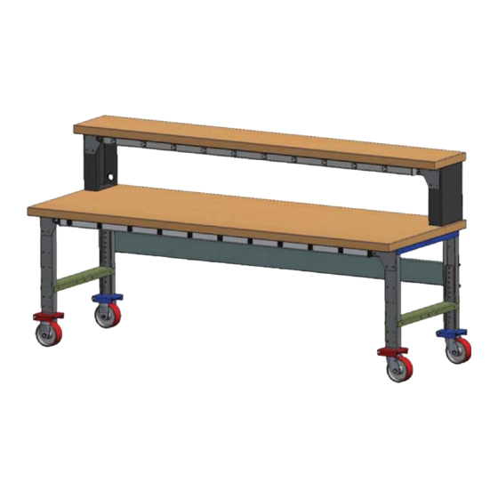
- Page 5 Attach the optional risers to the worksurface using (3) #14 x 1” lag bolts per riser. Once the riser is attached to the top set the shelf on the risers and attach using (3) #14 x 1” lag bolts per riser. #14 x 1”...
Need help?
Do you have a question about the GP Series and is the answer not in the manual?
Questions and answers