
Summary of Contents for Potter IntelliCheck LRM
- Page 1 IntelliCheck ™ Advanced Leak Rate Monitor Installation, Operation, and Instruction Manual St. Louis, MO Manual #5403773-A 11/20 800-325-3936 www.pottersignal.com...
- Page 2 Many States, Localities and Countries have codes and regulations governing sales, construction, installation, and/or use of products for certain purposes, which may vary from those in neighboring areas. While Potter attempts to assure that its products comply with such codes, it cannot guarantee compliance, and cannot be responsible for how the product is installed or used. Before purchase and use of a product, please review the product application, and national and local codes and regulations, and be sure that the product, installation, and use will comply with them.
-
Page 3: Table Of Contents
LRM • 5403773 • REV A • 11/20 Contents Safety Guidelines ................................4 Important Notice to Users ..............................4 Unpacking ................................... 4 General Safety Information ..............................4 System Overview ................................6 LRM Controller ..................................6 IntelliCheck Exterior View ..............................7 IntelliCheck Interior View ..............................8 LRM Display .................................. -
Page 4: Safety Guidelines
This manual contains safety information that is important to know and understand. This information is provided for the safety of installers, operators, and users of the Potter Leak Rate Monitor as well as attached equipment. To help recognize this information, observe the following symbols. - Page 5 The warnings in this manual cover most known potential hazards, but by definition cannot be all-inclusive. If the user employs an operating procedure, item of equipment, or a method of working that is not specifically recommended by Potter Electric Signal Company, the user must ensure that the equipment will not be damaged or become hazardous to persons or property.
-
Page 6: System Overview
System Overview The Potter IntelliCheck Advanced Leak Rate Monitor (LRM) is specifically designed to provide similar data as our Intelligen controller on existing or new systems that may not utilize our Intelligen N2 Generators as well as a system that utilizes a nitrogen generator to supply supervisory gas to multiple systems. -
Page 7: Intellicheck Exterior View
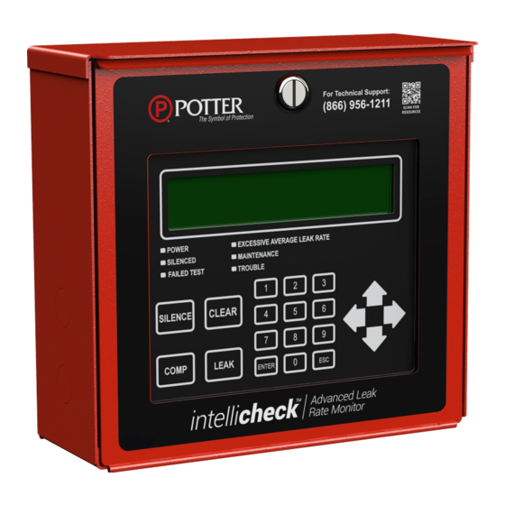
LRM • 5403773 • REV A • 11/20 IntelliCheck Exterior View Fig 1 1. LRM Display 2. LRM Housing 3. Knockouts for 1/2" Conduit Connection (Qty. 8) 4. ½” FNPT Pipe Connections 5. LRM Pressure Transducer 6. LRM Current Transformer 7. -
Page 8: Intellicheck Interior View
LRM • 5403773 • REV A • 11/20 IntelliCheck Interior View Fig 2 1. LRM Controller 2. Dip Switches 3. ¼” Mounting keyhole slots 4. Ethernet Port... -
Page 9: Lrm Display
LRM • 5403773 • REV A • 11/20 LRM Display: The LRM Display is the interface to the IntelliCheck. This display shows the LRM’s history, parameters, and troubles. Fig 3 LRM Display LED Light Indications: POWER – The green POWER LED indicates if the Leak Rate Monitor has power. SILENCED –... -
Page 10: Installation Of The Intellicheck
LRM • 5403773 • REV A • 11/20 Installation of the IntelliCheck NOTE: An accurate system size will increase the accuracy in calculating SCFM Loss On arrival, do a full inspection by checking all components in the packaging If damage is found, sign for the damage or refuse the shipment. Contact the carrier immediately and file a shipping damage claim with the carrier. -
Page 11: Suggested Install Diagrams
LRM • 5403773 • REV A • 11/20 Suggested Install With Tank Fig 6 SUPERVISORY MAINTENANCE SUPERVI GAS SUPPLY DEVICE GAS SU TANK PRESSURE TRANSDUCER SOLENOID CHECK RISER VALVE Suggested Tankless Install Fig 7 PRESSURE TRANSDUCER SUPERVISORY MAINTENANCE GAS SUPPLY DEVICE TANK SUPERVISORY... -
Page 12: Wiring Diagram
LRM • 5403773 • REV A • 11/20 Fig 8 LRM ENCLOSURE WHITE FERRITE BLACK TRANSDUCER CURRENT TRANSFORMER BLACK BLACK WHITE FERRITE WHITE BLACK BLUE POWER GREEN BROWN FERRITE SUPPLY SOLENOID LRM Transducer Installation LRM Transducer must be installed within reach of the provided 6ft transducer cable to the LRM Display Install ½”... -
Page 13: Intellicheck Startup
LRM • 5403773 • REV A • 11/20 Insert supplied solenoid DIN cable onto the solenoid and run the opposite end through a supplied strain relief fitting and a knockout on the LRM Housing Insert wires into the bottom 3-terminals of the 10-terminal block by depressing orange tab, inserting wire, and releasing tab on the LRM Controller per the Fig 8 wiring diagram on page 12 IntelliCheck Startup Apply power to the IntelliCheck... -
Page 14: Setting Sprinkler System Pressure Limits
LRM • 5403773 • REV A • 11/20 Sprinkler System Pressure Limits The LRM low pressure set point needs to be set using the system pressure displayed. The LRM's system pressure will need to correlate with the gauge on the sprinkler system. If the pressure displayed on the LRM does not correlate with the system pressure gauge, further investigation to identify the cause may be required. -
Page 15: Leak Rate Test Operation
LRM • 5403773 • REV A • 11/20 Leak Rate Test Operation Initiating a Leak Rate Test Press "ENTER" on the LRM Display keypad. Select "Settings" using the keypad. Press "ENTER". Enter passcode "0000". Select "Leak Rate". Press "ENTER". Select: 1. -
Page 16: Intelliview™ Dashboard Connectivity
IntelliView™ Dashboard Internet Connectivity Potter's LRM Controller is designed to provide you with live status updates of your IntelliCheck. The IntelliCheck needs to be wired using a Cat 5 Ethernet cable. The Ethernet port is located on the top left of the LRM Controller. When the unit is connected to the internet and powered on, data will be accessible at www.potterintelliview.com. - Page 17 LRM • 5403773 • REV A • 11/20 Trouble Alert #5 - Pressure Transducer Issue Issue: Transducer not detected by LRM Controller Probable Cause: Transducer cable has bad connection or is not plugged in Damage to transducer cable Bad transducer Trouble Alert #6 - Low Pressure Limit Exceeded Issue: System pressure has gone below lower set point limit Probable Cause:...
-
Page 18: Intellicheck Dimensional Drawings
LRM • 5403773 • REV A • 11/20 LRM Housing Dimensional Drawing Fig 9 DATE Fig 11 Fig 10 2.86in 72.54mm 1/2" FNPT 1/2" FNPT CHECK VALVE Fig 12 Fig 13 VENDOR CERTIFICATION... -
Page 19: Menu Trees
LRM • 5403773 • REV A • 11/20 Menu Trees 1. Main Menu... - Page 20 LRM • 5403773 • REV A • 11/20 2. System Status Menu 3. View History Menu 4. Maintenance Menu...
- Page 21 LRM • 5403773 • REV A • 11/20 5. System Settings Menu 6. Network Settings Menu...
- Page 22 LRM • 5403773 • REV A • 11/20 7. Leak Rate Settings Menu 8. Compressor Settings Menu...
Need help?
Do you have a question about the IntelliCheck LRM and is the answer not in the manual?
Questions and answers