Table of Contents
Advertisement
Advertisement
Table of Contents

Related Manuals for Garmin GMA 342


Summary of Contents for Garmin GMA 342
- Page 1 GMA 342/345 Installation Manual 190-01878-02 November, 2020 Revision 5...
- Page 2 ©2017 The Bluetooth ® word mark and logos are registered trademarks owned by Bluetooth SIG, Inc. and any use of such marks by Garmin is under license. Other trademarks and trade names are those of their respective owners. Garmin International, Inc.
- Page 3 California to cause cancer, birth defects, or reproductive harm. This Notice is being provided in accordance with California's Proposition 65. If you have any questions or would like additional information, please refer to our web site at www.garmin.com/prop65. NOTE Unless otherwise noted, information listed for the GMA 345 also applies to the GMA 345 3-COM version unit.
- Page 4 Software are valuable trade secrets of Garmin and/or its third-party providers and that the Software in source code form remains a valuable trade secret of Garmin and/or its third-party providers. You agree not to reproduce, decompile, disassemble, modify, reverse assemble, reverse engineer, or reduce to human readable form the Software or any part thereof or create any derivative works based on the Software.
-
Page 5: Table Of Contents
3.10 Disabling Bluetooth Connectivity (GMA 345 only) ............. 3-8 Section 4 System Interconnects .................4-1 4.1 Connector Description ..................... 4-1 4.2 Pin List ..........................4-1 4.3 Aircraft Power........................4-4 4.4 Lighting Bus ........................4-5 4.5 RS-232 ..........................4-5 190-01878-02 GMA 342/345 Installation Manual Rev. 5 Page iii... -
Page 6: Paragraph Page
Appendix A Installation Considerations for Upgrading from a Garmin GMA 340 ................A-1 A.1 Mechanical Considerations .................... A-1 A.2 Electrical Considerations ....................A-1 A.3 GMA 340 to GMA 342/345 Retrofit Connections ............A-2 Appendix B Outline and Installation Drawings ..........B-1 Appendix C Interconnect Drawings..............C-1 190-01878-02 GMA 342/345 Installation Manual Rev. -
Page 7: Section 1 General Description
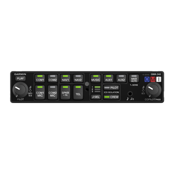
The GMA 345 has 2 music inputs in addition to the Bluetooth transceiver, NAV, COM, and ICS selections. The GMA 342 has 2 music inputs in addition to the front panel 3.5 mm jack, NAV, COM, and ICS selections. Both the GMA 345 and GMA 342 are easily configurable without an external PC connection. - Page 8 NOTE Unless otherwise noted, information listed for the GMA 345 also applies to the GMA 345 3-COM version unit. 1.2.1 Features Summary Table 1-1 GMA 342/345 Features Summary Feature GMA 342 GMA 345 GMA 345 3-COM Bluetooth Transceiver None 1 - Not shared with Music 1 or Music 2...
-
Page 9: Technical Specifications
Qualification Form. This form is available directly from Garmin under the following part number: GMA 34X Environmental Qualification Form, Garmin part number 005-00880-01 To obtain a copy of this form, see the dealer/OEM portion of the Garmin web site (www.garmin.com). 1.3.1... - Page 10 Overpressure - 15,000 Feet Maximum Days of Continuous Operation Dedicated Transceiver inputs: 3 (including TEL) for GMA 342 and 345, 4 (including TEL) for GMA 345 3-COM unit Dedicated Receiver inputs: 5 (per notes in Table 1-1 regarding which AUX...
- Page 11 The USB charge port will shutdown and protect the GMA 345 for current draw above 2.3 Amps. The GMA 342 has a standard 3.5 mm front panel jack for connecting by cable phones or tablets. The front panel allows stereo music to be played from a device, and also allows cell phone calls to be made through the GMA 342.
- Page 12 1.3.3 Power Requirements The GMA 342/345 will operate down to emergency voltage (9 Volts). Below 11 Volts, the USB charge port (GMA 345 only) and the speaker (both GMA 342 and GMA 345) are disabled. Table 1-5 GMA 342/345 Power Requirements...
-
Page 13: Certification
The Appliance Project Identifier (API) for the GMA 342 and GMA 345 is GMN-01319. The API has been used for project identification with the FAA. See applicable hardware and software part numbers to identify appliance approvals. - Page 14 Garmin received a deviation from TSO-C35d to not permanently and legibly marking the unit with each TSO’s required information. Garmin received a deviation from TSO-C35d to use FAR §45.15(b) instead of FAR TSO-C35d §37.7(d) as the general rules governing holders of the TSO authorizations.
- Page 15 3. Declaration of Conformity (GMA 345) Hereby, Garmin declares that this product is in compliance with the Directive 2014/53/EU. The full text of the EU declaration of conformity is available at the following internet address: www.garmin.com/compliance.
-
Page 16: Operating Instructions
GMA 345 Pilot’s Guide (190-01878-01), or GMA 345 3-COM Pilot’s Guide (190-01878-05). 1.6 Reference Documents The following publications are sources of additional information for installing the GMA 342/345. The installer should read all referenced materials along with this manual before attempting installation. -
Page 17: Introduction
2 INSTALLATION OVERVIEW 2.1 Introduction This section provides the necessary information for the installation and checkout of the GMA 342/345 Audio Panel. Installation of the GMA 342/345 will differ according to equipment location and other factors. The appendices contain interconnect wiring diagrams, mounting dimensions, and information pertaining to installation. -
Page 18: Available Accessories
Connector Plate Assembly, DCP 125-00040-00 Nut, Std, English, SS, #6-32 210-00036-07 Screw, 4-40 x 0.250, PHP, SS/P, w/NYL 211-60234-08 Table 2-5 Contents of GMA 342/345 Conn Kit (011-02302-00, also used for GMA 35/350) Item Part Number Quantity Backshell w/Hardware 44 pin 011-00950-02... - Page 19 • Heat shrink tubing • SD card needed for updating software in the GMA 342/345. Garmin recommends using a 4 GB Sandisk® SD card. Insulating Washers for Headset and Microphone Jacks can be found at the following suppliers: Dallas Avionics...
-
Page 20: Installation Considerations
For the GMA 345 3-COM unit, a single AUX button is used to select all 3 AUX inputs for simultaneous monitoring. For the GMA 342 and 345 (2-COM version), two buttons (AUX1 and AUX2) are used to select/deselect the 3 AUX inputs. Pressing the AUX1 button selects/deselects the AUX 1 and AUX 3 receivers. Pressing the AUX2 button selects/deselects the AUX 2 receiver. - Page 21 Avoid routing cables near power sources (e.g., 400 Hz generators, trim motors, etc.) or near power for fluorescent lighting • Allow a 12 inch minimum separation between any other cables, including antenna cables (e.g ADF, COM, NAV, GS, MARKER) 190-01878-02 GMA 342/345 Installation Manual Rev. 5 Page 2-5...
- Page 22 M17/128-RG400 terminated into a high density D-Sub connector. Refer to Table 2-8 for Crimp Tool, Pin, and Crimp Tool Insert part numbers. Figure 2-1 GMA 342/345 Marker Beacon Coaxial Cable D-Sub Termination Table 2-8 Pin and Crimp Tool Part Numbers...
-
Page 23: Cabling And Wiring
(DC) resistance less than or equal to 2.5 milliohms to local structure to where the equipment is mounted. Compliance should be verified by inspection using a calibrated milliohm meter. 190-01878-02 GMA 342/345 Installation Manual Rev. 5 Page 2-7... -
Page 24: Cooling Air
2.7 Cooling Air The GMA 342/345 does not have provisions for attaching cooling air, however the thermal characteristics of the installation should always be assessed. An undesirable thermal condition could be created due to the unit's own internal power dissipation combined with restricted ventilation, or due to heat generated by adjacent equipment. - Page 25 LEAVE SWITCH IN OFF POSTION RESERVED LEAVE SWITCH IN OFF POSTION RESERVED LEAVE SWITCH IN OFF POSTION CONFIGURATION When set to ON, this prevents use of the GMA 342/345 config mode LOCKOUT 190-01878-02 GMA 342/345 Installation Manual Rev. 5 Page 2-9...
- Page 26 The LEDs in the Level Bar (Figure 2-3) light to indicate an increase/decrease in the selected setting. • Pressing COM1 and MKR buttons simultaneously resets the configuration and operating state back to factory defaults. 190-01878-02 GMA 342/345 Installation Manual Rev. 5 Page 2-10...
- Page 27 ALERT 1, 2, 3, 4; OPTIONS: LEVELS OR DISABLING OPTIONS. WIRED TELEPHONE; MARKER BEACON; SPEAKER; PRESSING CYCLES THROUGH OPTIONS SPEAKER PA). (COCKPIT HIGH NOISE, MUSIC DURING ISOLATION). Figure 2-3 Front Panel Configuration 190-01878-02 GMA 342/345 Installation Manual Rev. 5 Page 2-11...
- Page 28 Input grounded, will allow microphone audio to the intercom KEY* from Copilot MIC. PA MODE This output is active when the GMA 342/345 is in PA J3402 Output SELECTED* mode. This output is active when the GMA 342/345 is in PA...
-
Page 29: Updating Software
2.9.1 Checking Software Version The GMA 342/345 comes pre-loaded with system software. However, if the software is out of date, it is recommended that current software be loaded from an SD card into the GMA 342/345. The current version of software can be retrieved in the configuration operating mode. See Section 2.8.6... -
Page 30: Electrical Noise
6. If a problem is encountered during the update process, follow the below steps for possible solutions. a) Use the Pilot Knob to power cycle the GMA 342/345, then perform the process again. b) Attempt to re-download the GMA 342/345 software to the PC, recreating the loader SD card, and perform the process again. -
Page 31: Mounting Requirements
2.11 Mounting Requirements The GMA 342/345 mounting surface must be capable of providing structural support and electrical bond to the aircraft to minimize radiated EMI and provide protection from High-Intensity Radiation Fields (HIRF). The GMA 342/345 is mounted using a GMA unit rack (Figure 2-4). See Section 3.6... -
Page 32: Section 3 Installation Procedure
Military P/N M39029/58-360 *Used for 18 AWG wire, is not included in the GMA 342/345 installation kits, and is not needed to install a GMA 342/345. GPN 336-00021-00 is used for 22 AWG wire and is included in the GMA 342/345 installation kits. -
Page 33: Antenna Installation
615725 M81969/1-04 NOTE 1. Non-Garmin part numbers shown are not maintained by Garmin and consequently are subject to change without notice. 2. Extracting #18 and #20 contacts requires that the expanded wire barrel be cut off from the contact. It may also be necessary to push the pin out from the face of the connector when using an extractor due to the absence of the wire. -
Page 34: Backshell Assembly
3. Mount the GMA 342/345 to the GMA rack as shown on the installation drawing. 4. Assemble the rear plate into the GMA 342/345 unit rack. 5. Insert the GMA 342/345 into the rack, noting proper orientation as shown on the installation drawing. -
Page 35: Post Installation Checkout
2. Verify each installed unswitched (alert) source can be heard when the source is instructed to play a simulated alert/message. NOTE For the GMA 342 and 345 (2-COM version) unit AUX inputs, pressing the AUX1 button selects/deselects the AUX 1 and the AUX 3 receiver. Pressing the AUX2 button selects/ deselects the AUX 2 receiver. - Page 36 3.7.4 Music System Check 1. Set GMA 342/345 to ALL mode with Pilot and Crew button off. 2. Connect a stereo audio source to MUSIC 1. Verify that stereo audio is heard over all headset positions when MUSIC 1 is selected as the music source and the MUSIC LED is on. Verify that music volume adjustment is working properly for Pilot, Copilot, and Passengers (if passenger headsets are wired).
- Page 37 Speaker Check 1. If a speaker was installed, select SPKR and receive COM audio on the selected COM. When the speaker is selected, the selected Receivers on the GMA 342/345 (COM, NAV, AUX) should be heard from the speaker. 2. Initiate PA (Passenger Address) mode and verify that from both the pilot and copilot position, the crew position that is pressing PTT has the respective mic audio delivered to the speaker clearly.
-
Page 38: Continued Airworthiness
GMA 342/345 is not required. 3.9 Diagnostics Information The GMA 342/345 is capable of displaying diagnostics information while in normal mode of operation. To show the diagnostics information press the PLAY button for five seconds. While still holding the PLAY button, all button annunciators will turn off except for those associated with certain diagnostic states. -
Page 39: Disabling Bluetooth Connectivity (Gma 345 Only)
4. An audio clip will be heard in the headset that says “Bluetooth Enabled”. NOTE Once disabled, the GMA 345 Bluetooth connectivity does not remain disabled after power cycling. The GMA 345 Bluetooth connectivity is always enabled following a power cycle. 190-01878-02 GMA 342/345 Installation Manual Rev. 5 Page 3-8... -
Page 40: Section 4 System Interconnects
4.1 Connector Description The GMA 342/345 has two 44-pin connectors located at the rear of the unit designated J3401 and J3402 which are oriented as shown in Figure 4-1. The GMA 342/345 is installed into a rack with shield block backshells. - Page 41 Table 4-1 J3401 Pin Assignments Pin Name WIRED TEL MIC OUT (GMA 342/345) COM 3 MIC OUT (GMA 345 3-COM unit only) RESERVED (GMA 342/345) COM 3 MIC KEY* OUT (GMA 345 3-COM unit only) RCVR 4 AUDIO IN HI (AUX 2)
- Page 42 ALERT 2 AUDIO IN HI PILOT HEADSET AUDIO OUT LEFT RS-232 IN RS-232 OUT PA MODE SELECTED* COM SWAP* GROUND PLAY KEY* *Denotes Active Low (Inputs: ground to activate; Outputs: grounded when active) 190-01878-02 GMA 342/345 Installation Manual Rev. 5 Page 4-3...
-
Page 43: Aircraft Power
4.3 Aircraft Power The GMA 342/345 has four pins for aircraft power bus inputs. Use one wire for each of the pins connecting to the aircraft power and ground. Do not splice the power and ground pins at the unit and use only one wire to aircraft power and ground. -
Page 44: Lighting Bus
4.4 Lighting Bus The GMA 342/345 can be configured to track a 14 or 28 Vdc lighting bus using these inputs. Refer to Appendix C for lighting interconnections. Backlighting refers only to the lighting of the text labels on the front panel and is controlled by the inputs in Table 4-4. - Page 45 PASS 3 MIC AUDIO IN LO J3402 PASS 4 MIC AUDIO IN HI Passenger 4 Mic audio and ground reference J3402 PASS 4 MIC AUDIO IN LO *Denotes Active Low (Ground to activate) 190-01878-02 GMA 342/345 Installation Manual Rev. 5 Page 4-6...
- Page 46 4.6.2 COM Audio and Mic Keys Table 4-7 COM Audio and Mic Keys (GMA 342/345 2-COM unit only) Connector Pin Name Description J3401 COM 1 MIC KEY* OUT Enables transmission on the respective transceiver unit J3401 COM 2 MIC KEY* OUT...
- Page 47 NAV 2 Ground Reference NOTE For GMA 342/345 2-COM units only, two buttons (AUX1 and AUX2) are used to select/ deselect the 3 AUX inputs. Pressing the AUX1 button selects/deselects the AUX 1 and AUX 3 receivers. Pressing the AUX2 button selects/deselects the AUX 2 receiver.
- Page 48 4.6.5 Failsafe Warning Audio Failsafe audio is audio from another device that is heard when the GMA 342/345 is in failsafe mode (power off or unit failure) and is desired to be heard in addition to the COM audio. Table 4-11 Failsafe Warning Audio...
- Page 49 GMA 342/345. A true mono headset will work correctly with the GMA 342/345, but only mono (left channel) audio will be heard, and 3D audio will not be available (even if enabled). The GMA 342/345 will detect the mono headset (if stereo jacks are used), and automatically switch to mono operation. 3D audio is not available with mono headsets or in installations that use mono jacks for the headsets.
- Page 50 Do not connect the LO of the speaker to the aircraft chassis. Two wires must be connected from the GMA 342/345 to the Speaker for the HI and LO signals. If speaker LO is connected to the aircraft chassis ground, the speaker will contain more noise than if connected back to the GMA 342/345 source connections.
-
Page 51: Discrete Inputs
Pin Name J3401 MARKER ANTENNA IN HI J3401 MARKER ANTENNA IN LO J3401 INNER MARKER LAMP OUT J3401 OUTER MARKER LAMP OUT J3401 MIDDLE MARKER LAMP OUT J3401 MIDDLE MARKER SENSE OUT 190-01878-02 GMA 342/345 Installation Manual Rev. 5 Page 4-12... -
Page 52: Appendix A Installation Considerations For Upgrading From Agarmin Gma 340
The GMA 340 connectors are compatible and may be reused. If replacing a GMA 340 with a GMA 342/345, the GMA 340 (330-00220-25) connector backshells can be reused. However, grounding the wire shields to the GMA 342/345 will be easier with the Garmin backshells in GPN 011-02302-00. -
Page 53: Gma 340 To Gma 342/345 Retrofit Connections
8 OHM SELECT* RESERVED BUTTON PRESS TONE ENABLE* PA MODE SELECTED* NO CONNECT PLAY KEY* MUTE ON COM TX* IN COPILOT ICS KEY* Figure A-1 GMA 340 to GMA 342/345 Retrofit Connections 190-01878-02 GMA 342/345 Installation Manual Rev. 5 Page A-2... - Page 54 (4 PLACES PER SIDE) 1.28 32.4 4X .025 0.64 1.30 33.0 .94 23.8 .60 15.2 .65 16.5 2X .35 8.9 .5 13 .44 11.1 3.49 88.6 5.16 131.1 Figure B-1 GMA 342/345 Outline Drawing 190-01878-02 GMA 342/345 Installation Manual Revision 5 Page B-1...
-
Page 55: Appendix B Outline And Installation Drawings
APPENDIX B OUTLINE AND INSTALLATION DRAWINGS GMA 342/345 BACK PLATE (ALSO USED ON GMA 240/340) SUB-ASSEMBLY 011-00678-00 GMA 342/345 CONNECTOR KIT (ALSO USED ON GMA 35/350) 011-02302-00 Figure B-2 GMA 342/345 Installation Drawing 190-01878-02 GMA 342/345 Installation Manual Revision 5 Page B-2... - Page 56 2. IF THE FRONT LIP OF THE MOUNTING RACK IS BEHIND THE SURFACE OF THE AIRCRAFT PANEL THE UNIT CONNECTORS MAY NOT FULLY ENGAGE. 6.18 157.0 Figure B-3 GMA 342/345 Panel Cutout Drawing 190-01878-02 GMA 342/345 Installation Manual Revision 5 Page B-3...
- Page 57 10. THE LIGHTING BUS VOLTAGE RANGE IS CONFIGURABLE FOR EITHER 14 OR 28 VOLT SYSTEMS. REFER TO INSTALL MANUAL CONFIGURATION OPTIONS. 11. GARMIN RECOMMENDS USING STEREO HEADPHONES. IF MONO JACKS ARE DESIRED, GARMIN RECOMMENDS THE USE OF THE LEFT OUTPUT ONLY (LEAVE THE RIGHT CHANNEL UNCONNECTED). DO NOT CONNECT THE LEFT AND RIGHT CHANNELS TOGETHER.
- Page 58 Inhibit Input of Applicable COM ACTIVE* OUT Audio Source MARKER BEACON ANTENNA MARKER ANTENNA HIGH MARKER ANTENNA LO SEE NOTE 20 NO CONNECT PINS 6,25,26,27,28 Figure C-2 J3401 Connector Example Interconnect Drawing 190-01878-02 GMA 342/345 Installation Manual Revision 5 Page C-2...
- Page 59 SPARE GROUND CAN BE USED FOR ANY GROUND RETURN EXCEPT POWER OR MUSIC. DO NOT USE FOR POWER OR MUSIC GROUND. RS-232 IN RS-232 OUT Figure C-3 J3402 Connector Example Interconnect Drawing 190-01878-02 GMA 342/345 Installation Manual Revision 5 Page C-3...
- Page 60 TO 28 VOLT LIGHTING BUS LO IF NEITHER OF THE ABOVE LIGHTING BUS CONFIGURATIONS ARE WIRED, THE UNIT WILL DEFAULT TO USE THE DISPLAY PHOTOCELL FOR LIGHTING CONTROL Figure C-4 Lighting Bus Example Interconnect Drawing 190-01878-02 GMA 342/345 Installation Manual Revision 5 Page C-4...
- Page 61 MUSIC 1 IN RIGHT MONO AUDIO SOURCE MONO AUDIO OUT HI MUSIC 2 IN LEFT MUSIC 2 IN LO MONO AUDIO OUT LO MUSIC 2 IN RIGHT Figure C-5 Mono Audio Example Interconnect Drawing 190-01878-02 GMA 342/345 Installation Manual Revision 5 Page C-5...
- Page 62 GMA 342/345 J3401 P3401 PASSENGER HEADSET PARALLEL WIRING UP TO 4 JACKS NOTE 5 PASS HEADSET LO PASS HEADSET RIGHT PASS HEADSET LEFT Figure C-6 Four Passenger Headset Wiring Example Interconnect Drawing 190-01878-02 GMA 342/345 Installation Manual Revision 5 Page C-6...
- Page 63 PTT* MIC HI 5. MIC HI WHT/BLU MIC LO 6. MIC LO PTT* ALL SPLICES FROM LEMO JACK OCCUR AT GMA END OF HARNESS Figure C-7 LEMO Connector Example Interconnect Drawing 190-01878-02 GMA 342/345 Installation Manual Revision 5 Page C-7...
- Page 64 AUDIO IN HI AUDIO IN LO AUDIO IN HI AUDIO IN LO KEY* IN AUDIO IN HI AUDIO OUT RIGHT Figure C-8 J3401 & J3402 Connector Layout Drawing (not applicable to 3-COM Units) 190-01878-02 GMA 342/345 Installation Manual Revision 5 Page C-8...
- Page 65 AUDIO IN HI AUDIO IN LO AUDIO IN HI AUDIO IN LO KEY* IN AUDIO IN HI AUDIO OUT RIGHT Figure C-9 J3401 & J3402 Connector Layout Drawing for 3-COM units 190-01878-02 GMA 342/345 Installation Manual Revision 5 Page C-9...
Need help?
Do you have a question about the GMA 342 and is the answer not in the manual?
Questions and answers