Table of Contents
Advertisement
Quick Links
Advertisement
Table of Contents

Related Manuals for Artifex LDD100-F Series

Summary of Contents for Artifex LDD100-F Series
- Page 1 Artifex Engineering LDD100-Fxxx LDD100-Lxxx LDD100-XLxxx Laser Diode Driver Read this instruction manual before performing any task! Artifex Dortmunder Str. 16-18 26723 Emden, Germany Tel: +49-(0)4921-58908-0 Engineering Fax: +49-(0)4921-58908-29 info@afx-eng.com http://www.afx-eng.com...
- Page 2 LDD100 Operating Instructions Original Operating Instructions Artifex Engineering GmbH & Co. KG. Dortmunder Str. 16-18 26723 Emden Germany Telephone: +49-(0)4921-58908-0 Fax: +49-(0)4921-58908-29 Email: info@artifex-engineering.com Internet: www.artifex-engineering.com Artifex Engineering GmbH & Co. KG., 2020 2 / 72...
-
Page 3: Table Of Contents
LDD100 Operating Instructions Table of Contents ABOUT THIS MANUAL Information about this manual Explanation of symbols Copyright Customer service SAFETY Intended use Basic dangers Responsibility of the owner Personnel requirements Symbols on the unit Scope of delivery Transport inspection Packaging Transporting 2.10 Storage... - Page 4 LDD100 Operating Instructions SPECIFICATIONS Specifications: LDD100-F040 5.1.1 Safe Operating Area (LDD100-F040) Specifications: LDD100-F120 5.2.1 Safe Operating Area (LDD100-F120) Specifications: LDD100-L040 5.3.1 Safe Operating Area (LDD100-L040) 5.3.2 Safe Operating Area (LDD100-L120) Specifications: LDD100-L200 5.4.1 Safe Operating Area (LDD100-L200) Specifications: LDD100-XL040 5.5.1 Safe Operating Area (LDD100-XL040) Specifications: LDD100-XL120 5.6.1 Safe Operating Area (LDD100-XL120) Specifications: LDD100-XL200...
- Page 5 LDD100 Operating Instructions 6.1.10 Stop Button 6.1.11 Start/Pause Button Back Panel (Control Unit) 6.2.1 Power Supply 6.2.2 Laser Head Power 6.2.3 Laser Head Communication 6.2.4 Signal Lamp 6.2.5 USB 6.2.6 Interlock 6.2.7 Trigger Out 6.2.8 Trigger In Front Panel (Current Driver End Stage Unit) 6.3.1 Current Output Back Panel (Current Driver End Stage Unit) 6.4.1 Communication...
- Page 6 LDD100 Operating Instructions 10.1.10 Field “Exit” COMMUNICATION 11.1 Connection 11.2 Parameter Upload 11.2.1 Pulse Duration 11.2.2 Pulse Repetition Period 11.2.3 Current Steps 11.2.4 Bias 11.2.5 Number of cycles 11.2.6 Cycling mode 11.2.7 Continuous Mode 11.2.8 Starting a sequence 11.2.9 Stop a sequence 11.2.10 Read status and temperature of the laser driver 11.3 The SDK Package...
- Page 7 LDD100 Operating Instructions List of Figures Figure 1: System Overview ...................... 19 Figure 2: LDD100-F040; 2µs, 40A pulse shape ..............22 Figure 3: LDD100-L200; 200A pulse (10µs); 20A pulse (10µs); 1A pulse (100µs) ....22 Figure 4: LDD100-XL200; 10µs, 200A pulse; 20A pulse; 2A pulse ........23 Figure 5: Front Panel ........................
- Page 8 LDD100 Operating Instructions List of Tables Table 1: Ordering Information F-Version ................22 Table 2: Ordering Information L-Version ................22 Table 3: Ordering Information XL-Version ................23 Table 4: Specifications LDD-F040 ..................24 Table 5: Specifications LDD-F120 ..................26 Table 6: Specifications LDD-L040 ..................28 Table 7: Specifications LDD-L120 ..................
-
Page 9: About This Manual
LDD100 Operating Instructions 1 About this manual 1.1 Information about this manual This manual is valid for units with firmware version FW3.0. This manual enables you to handle the device in a safe and efficient manner. This manual is part of the device and must be kept in its vicinity in order to ensure that it is available to the personnel at all times. - Page 10 LDD100 Operating Instructions CAUTION! This combination of symbol and signal word indicates a possibly- dangerous situation which could cause slight injuries if it is not avoided. NOTICE! This combination of symbol and signal word indicates a possibly-dangerous situation which could cause property and environmental damage if it is not avoided.
-
Page 11: Copyright
Any use extending beyond this is not allowed without written permission from the manufacturer. 1.4 Customer service Our customer service is available for technical information and service: Artifex Engineering GmbH & Co. KG. Dortmunder Str. 16-18 26723 Emden Germany... -
Page 12: Safety
LDD100 Operating Instructions 2 Safety This section provides an overview of all safety aspects that are essential to the best possible protection of the personnel and the safe and trouble-free operation of the machine. Additional safety instructions for specific work tasks are contained in the sections regarding the individual life stages of the machine. -
Page 13: Responsibility Of The Owner
LDD100 Operating Instructions 2.3 Responsibility of the owner Owner: The owner is any such person who operates the laser diode driver for commercial or economic purpose either by itself or transfers it to a third party for use and bears the legal responsibility for the safety of the user, the personnel or third parties during the operation. -
Page 14: Personnel Requirements
LDD100 Operating Instructions 2.4 Personnel requirements Qualifications: The various tasks described in this manual place different requirements on the qualification of the persons to whom these tasks are entrusted. NOTICE! Insufficiently qualified personnel can cause property damage! Insufficiently qualified personnel cannot assess the risks when working with the unit. -
Page 15: Symbols On The Unit
LDD100 Operating Instructions 2.5 Symbols on the unit The following symbols and instruction signs are affixed in the work area. These symbols and instruction signs refer to the immediate vicinity in which they are affixed. WARNING! Danger due to illegible signage! •... -
Page 16: Scope Of Delivery
LDD100 Operating Instructions 2.6 Scope of delivery Depending of the chosen model, the scope of delivery will vary: • LDD100 laser diode driver controller • Current end stage unit • Communication and power cables for the end stage unit • Mains power supply cable •... -
Page 17: Transporting
LDD100 Operating Instructions Handling packaging materials If the laser diode driver no longer has to be transported, dispose of the packaging materials in accordance with the respective statutory provisions and local regulations. NOTICE! Danger for the environment from improper disposal! Packaging materials are valuable raw materials and can be reused in many cases or prepared and recycled. -
Page 18: Storage
LDD100 Operating Instructions 2.10 Storage Store the electronic ballasts in the packaging under the following conditions: • Do not store outdoors. • Store in a dry and dust-free area. • Do not expose to any aggressive media. • Protect from sun radiation. •... -
Page 19: Product Overview
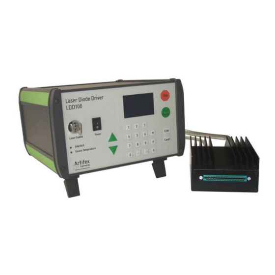
LDD100 Operating Instructions 3 Product Overview The LDD100 is a fast, true current source designed for driving laser diodes and high power LEDs. The LDD100 laser diode driver employs a digitally controlled analogue current source to provide for simple, flexible and accurate laser pulsing. These laser drivers are particularly useful for laser diode testing procedures such as burn-in and LIV measurement. -
Page 20: Modes Of Driving
LDD100 Operating Instructions 3.2 Modes of Driving The LDD100 supports a variety of modes to allow testing under a wide range of operating conditions. The essential variables available are the output current, pulse width and the pulse separation (or period or frequency). The various modes of operation are described in detail in the subsections below. -
Page 21: Pulse Mode
LDD100 Operating Instructions 3.2.3 Pulse Mode The pulse mode is used to pulse the driver at constant current with a single pulse width and pulse separation during the whole sequence. During a sequence, the programmed currents are sequentially set via the controller interface of the LDD100. -
Page 22: Ordering Information
LDD100 Operating Instructions 4 Ordering Information Table 1: Ordering Information F-Version Full order code: 100-F Options Description Maximum current (c): 120A 4.1 Typical Current Pulse Forms, F-Version Figure 2: LDD100-F040; 2µs, 40A pulse shape Table 2: Ordering Information L-Version Full order code: 100-L Options Description... -
Page 23: Typical Current Pulse Forms, Xl-Version
LDD100 Operating Instructions Table 3: Ordering Information XL-Version Full order code: 100-XL Options Description Maximum current (c): 120A 200A 400A 600A 4.3 Typical Current Pulse Forms, XL-Version Figure 4: LDD100-XL200; 10µs, 200A pulse; 20A pulse; 2A pulse For customized or OEM systems, please contact us. 23 / 72... -
Page 24: Specifications
LDD100 Operating Instructions 5 Specifications 5.1 Specifications: LDD100-F040 Table 4: Specifications LDD-F040 ARAMETER ONDITIONS NITS UTPUT Current 2µs pulse duration Bias current 1000 Current resolution Control unit to head LEMO Connector Head to laser Strip line Rise time / Fall time Pulse duration Resolution of pulse 50ns to 1.5ms... -
Page 25: Safe Operating Area (Ldd100-F040)
LDD100 Operating Instructions 5.1.1 Safe Operating Area (LDD100-F040) 25 / 72... -
Page 26: Specifications: Ldd100-F120
LDD100 Operating Instructions 5.2 Specifications: LDD100-F120 Table 5: Specifications LDD-F120 ARAMETER ONDITIONS NITS UTPUT Current 2µs pulse duration Bias current 1000 Current resolution Control unit to head LEMO Connector Head to laser Strip line Rise time / Fall time Pulse duration Resolution of pulse 50ns to 1.5ms duration... -
Page 27: Safe Operating Area (Ldd100-F120)
LDD100 Operating Instructions 5.2.1 Safe Operating Area (LDD100-F120) 27 / 72... -
Page 28: Specifications: Ldd100-L040
LDD100 Operating Instructions 5.3 Specifications: LDD100-L040 Table 6: Specifications LDD-L040 ARAMETER ONDITIONS NITS UTPUT Current 5 µs pulse duration Bias current 1000 Current resolution Control unit to head LEMO Connector Head to laser Strip line Rise time / Fall time Pulse duration Resolution of pulse 50ns to 1.5ms... -
Page 29: Safe Operating Area (Ldd100-L040)
LDD100 Operating Instructions 5.3.1 Safe Operating Area (LDD100-L040) 29 / 72... -
Page 30: Table 7: Specifications Ldd-L120
LDD100 Operating Instructions Specifications: LDD100-L120 Table 7: Specifications LDD-L120 ARAMETER ONDITIONS NITS UTPUT Current 5 µs pulse duration Bias current 1000 Current resolution Control unit to head LEMO Connector Head to laser Strip line Rise time / Fall time Pulse duration Resolution of pulse 50ns to 1.5ms duration... -
Page 31: Safe Operating Area (Ldd100-L120)
LDD100 Operating Instructions 5.3.2 Safe Operating Area (LDD100-L120) 31 / 72... -
Page 32: Specifications: Ldd100-L200
LDD100 Operating Instructions 5.4 Specifications: LDD100-L200 Table 8: Specifications LDD-L200 ARAMETER ONDITIONS NITS UTPUT Current 5 µs pulse duration Bias current 1000 Current resolution Control unit to head LEMO Connector Head to laser Strip line Rise time / Fall time Pulse duration Resolution of pulse 50ns to 1.5ms... -
Page 33: Safe Operating Area (Ldd100-L200)
LDD100 Operating Instructions 5.4.1 Safe Operating Area (LDD100-L200) 33 / 72... -
Page 34: Specifications: Ldd100-Xl040
LDD100 Operating Instructions 5.5 Specifications: LDD100-XL040 Table 9: Specifications LDD-XL040 ARAMETER ONDITIONS NITS UTPUT Current 10 µs pulse duration Bias current 1000 Current resolution Control unit to head LEMO Connector Head to laser Strip line Rise time / Fall time µs Pulse duration Resolution of pulse... -
Page 35: Safe Operating Area (Ldd100-Xl040)
LDD100 Operating Instructions 5.5.1 Safe Operating Area (LDD100-XL040) 35 / 72... -
Page 36: Specifications: Ldd100-Xl120
LDD100 Operating Instructions 5.6 Specifications: LDD100-XL120 Table 10: Specifications LDD-XL120 ARAMETER ONDITIONS NITS UTPUT Current 10µs pulse duration Bias current 2000 Current resolution Control unit to head LEMO Connector Head to laser Strip line Rise time / Fall time µs Pulse duration Resolution of pulse 50ns to 1.5ms... -
Page 37: Safe Operating Area (Ldd100-Xl120)
LDD100 Operating Instructions 5.6.1 Safe Operating Area (LDD100-XL120) 37 / 72... -
Page 38: Specifications: Ldd100-Xl200
LDD100 Operating Instructions 5.7 Specifications: LDD100-XL200 Table 11: Specifications LDD-XL200 ARAMETER ONDITIONS NITS UTPUT Current 10µs pulse duration Bias current 2000 Current resolution Control unit to head LEMO Connector Head to laser Strip line Rise time / Fall time µs Pulse duration Resolution of pulse 50ns to 1.5ms... -
Page 39: Safe Operating Area (Ldd100-Xl200)
LDD100 Operating Instructions 5.7.1 Safe Operating Area (LDD100-XL200) 39 / 72... -
Page 40: Specifications: Ldd100-Xl400
LDD100 Operating Instructions 5.8 Specifications: LDD100-XL400 Table 12: Specifications LDD-XL400 ARAMETER ONDITIONS NITS UTPUT Current 10µs pulse duration Bias current 2000 Current resolution Control unit to head LEMO Connector Head to laser Strip line Rise time / Fall time µs Pulse duration Resolution of pulse 50ns to 1.5ms... -
Page 41: Safe Operating Area (Ldd100-Xl400)
LDD100 Operating Instructions 5.8.1 Safe Operating Area (LDD100-XL400) 41 / 72... -
Page 42: Specifications: Ldd100-Xl600
LDD100 Operating Instructions 5.9 Specifications: LDD100-XL600 Table 13: Specifications LDD-XL600 ARAMETER ONDITIONS NITS UTPUT Current 10µs pulse duration Bias current 2000 Current resolution Control unit to head LEMO Connector Head to laser Strip line Rise time / Fall time µs Pulse duration Resolution of pulse 50ns to 1.5ms... -
Page 43: Safe Operating Area (Ldd100-Xl600)
LDD100 Operating Instructions 5.9.1 Safe Operating Area (LDD100-XL600) 43 / 72... -
Page 44: Case Dimensions (Mm [Inch])
LDD100 Operating Instructions 5.10 Case Dimensions (mm [inch]) 6 Connections 6.1 Front Panel (Control Unit) Figure 5: Front Panel 44 / 72... -
Page 45: Power Switch
LDD100 Operating Instructions 6.1.1 Power Switch The power switch activates the internal power supply for the control unit. The control unit is active, but not enabled to drive current unless the key switch is also turned on. 6.1.2 Key Switch (Laser Enable) The key switch enables and disables the current driver. -
Page 46: Back Panel (Control Unit)
LDD100 Operating Instructions 6.2 Back Panel (Control Unit) Figure 6: Back Panel 6.2.1 Power Supply This receptacle connects the mains power input to the control system. The input block contains a slow blow fuse which may be replaced by the user if required. The internal universal switching power supply is mains input rated at 85-264VAC, 48-62Hz. -
Page 47: Usb
LDD100 Operating Instructions 6.2.5 The communication with the LDD100 is via USB 2.0 with a baud rate of 1 000 000 bit/s. A hardware-handshake using RTS/CTS is employed to ensure secure communication. The appropriate USB cable is supplied with the system. The standard cable length is 2m. A 5m cable may be supplied upon request. -
Page 48: Front Panel (Current Driver End Stage Unit)
Contact card receptacle (current output) Artifex Engineering provides full support to design and manufacture custom strip line contact cards for contacting laser bars, chips, TO, C-Mount, CS-Mount, etc. Contact us for your requirements. The contact card is inserted into the card receptacle with the key slot on the left hand side of the receptacle. -
Page 49: Figure 7: Mounting A New Contact Card
LDD100 Operating Instructions NOTICE! The needles and pogo pins (laser contact pins) are sensitive. Do not touch the pins with your fingers or tools under any circumstance. The contact card is fitted with a card support when delivered. If for any reason you need to exchange cards on the support, remove the two screws holding the card support to the LDD unit and remove the complete card assembly in order to change cards. -
Page 50: Back Panel (Current Driver End Stage Unit)
LDD100 Operating Instructions 6.4 Back Panel (Current Driver End Stage Unit) Figure 8: Back Panel 6.4.1 Communication This receptacle connects the communication lines to the current driver end stage head. The connector is key coded to prevent insertion in the wrong direction. The red marks on the connector and the receptacle must be aligned in order to insert the connector. -
Page 51: Operation
LDD100 Operating Instructions 7 Operation The LDD100 may be controlled in one of three manners: 1. Control via the real front panel touchpad 2. Control via the virtual graphical user interface supplied with the unit 3. Control via customer own software which may be written around the core dll supplied with the unit 8 Control Via the (Real) Front Panel The touchpad front panel together with the OLED display on the front panel allow the user to... -
Page 52: Table 14: Menu Structure (Front Panel Control)
LDD100 Operating Instructions Table 14: Menu Structure (Front Panel Control) Main menu Submenu 1 Submenu 2 Submenu 3 Submenu 4 1/Sequence 1/Parallel 1/Current 1/Max value + unit 2/Min value + unit 3/Bias value + unit 2/No. of steps value 3/No. of cycles Number value Continuous mode... - Page 53 LDD100 Operating Instructions When the instrument is first turned on, the user will be prompted to enter the current limit. This is a safety feature to prevent damage of devices which cannot withstand the full current capability of the instrument. Following this, the OLED displays the following menu: 1/Sequence 2/Trigger...
- Page 54 LDD100 Operating Instructions When the instrument is shut down, the most recent active parameters are also automatically saved into a “default” non-volatile memory. Thus, when starting the instrument, the last used parameter set is automatically loaded. Additionally, the user may store or recall a setup profile into numerated non-volatile memories via the menu “Setup Profiles”.
-
Page 55: Installation Of The Software Package
LDD100 Operating Instructions 9 Installation of the Software Package The installation of the software package is described in a separate document provided with the instrument. 10 Using the GUI Application Software The graphical user interface is simple and easy to use. All of the important features can be reached directly in the main window. -
Page 56: Settings
LDD100 Operating Instructions 10.1 Settings The GUI is arranged in logical fields which are described in the sections below. 10.1.1 Field “Control” Figure 10: Field “Control” Start: Starts a sequence of current pulses. DANGER! The device under test will begin to emit potentially dangerous levels of laser power immediately after clicking the “Start”... -
Page 57: Field "Pulse Repetition
LDD100 Operating Instructions 10.1.3 Field “Pulse Repetition” Figure 12: Field “Pulse Repetition” Pulse repetition: Input an integer and select the units (ns, µs, ms) from the dropdown box in order to set the temporal value. The meaning of this value is determined by selection of one of the three radio buttons described below. -
Page 58: Field "Current Pulse Amplitude
LDD100 Operating Instructions 10.1.5 Field “Current Pulse Amplitude” Figure 14: Field “Current Pulse Amplitude” Min: Input an integer and select the units (mA, A) from the dropdown box in order to set the minimum current of the current pulse sequence to be driven. -
Page 59: Field "Setup Profiles
LDD100 Operating Instructions 10.1.6 Field “Setup Profiles” Figure 15: Field “Setup Profiles” Since the sequence involves setting up many parameters which may have potentially damaging effects on the laser under test, there is a provision for storing setup files. These files can be appropriately named and contain all of the parameters. -
Page 60: Field "Monitor
LDD100 Operating Instructions Radio button to activate the parallel sweep mode. This mode performs a current sweep by stepping the pulse current from the minimum set value to the maximum set value in a number of equidistant currents as determined by the parameter “Steps”. More than one cycle may be run automatically via the parameter “Number of Cycles”. -
Page 61: Field "Device
LDD100 Operating Instructions 10.1.9 Field “Device” Figure 18: Field “Device” Connect: When the system is first turned on and the GUI is started, the (real) touchpad front panel is the active control input panel. In order to transfer control to the GUI, the software must connect to the system. This action is performed by clicking the “Connect”... -
Page 62: Communication
LDD100 Operating Instructions 11 Communication Communication with the LDD100 is via USB 2.0. The most recent USB driver for the Microsoft Windows operating system is included on the storage medium shipped with the device. Following installation there will be two drivers in the device manager under “System Properties”. -
Page 63: Parameter Upload
LDD100 Operating Instructions Thereafter, the RTS line must be switched with a period of approximately 200ms, independent of all other communication. Delay of this switching will result in abortion of the communication connection. 11.2 Parameter Upload The parameter set has to be uploaded before any current pulse may be generated. In the upload process all data is send byte by byte. -
Page 64: Table 16: Error Codes
LDD100 Operating Instructions 0: Not Continuously Continuous Mode 0 - 1 1: Continuously Pulse Width Timer 0 – 250 0 – 150µs (600ns steps) Pulse Separation Timer (High Byte) 10µs – 1ms 200 - 20 000 range multiplier for Pulse Separation Timer (Low Byte) pulse separation Following upload of the parameter set, the instrument performs an internal test of the validity of the input values. -
Page 65: Figure 20: Schematic Representation Of The Parameter Upload
LDD100 Operating Instructions The parameter upload may visualized by the following flow chart: Figure 20: Schematic Representation of the Parameter Upload 65 / 72... -
Page 66: Pulse Duration
LDD100 Operating Instructions 11.2.1 Pulse Duration As for the pulse repetition period, the pulse duration is calculated via a base parameter (Byte 3 and Byte 4) as well as a timer (Pulse Width Timer (PWT): Byte 19). If the PWT is set to 0, the base parameter has a value of 50ns. -
Page 67: Current Steps
LDD100 Operating Instructions 11.2.3 Current Steps The number of equidistant steps when sweeping from the minimum to the maximum current. This is calculated as follows: Number of steps = (Byte 9 x 256) + Byte 10. 11.2.4 Bias This parameter sets the bias current. This value is limited to 1A and may be set with a resolution of 4095 = 0.244mA/bit. -
Page 68: Stop A Sequence
LDD100 Operating Instructions If Byte 33 “!” is returned, then the uploaded parameter set is not valid. @e – start a sequence with external Trigger. When the trigger signal rises, the full sequence is generated. If Byte 33 “!” is returned, then the uploaded parameter set is not valid. @E - start a single pulse of a sequence. -
Page 69: The Sdk Package
LDD100 Operating Instructions 11.3 The SDK Package The LDD100 comes with a software development kit (SDK package) in order to ease integration of the instrument into OEM projects. This package includes the source code of the application programme (written in Microsoft ... -
Page 70: Documentation For Labview Ldd100Com
LDD100 Operating Instructions 11.5 Documentation for LabVIEW LDD100Com.vi The LDD100 is delivered with a fully functional demo virtual instrument (VI). In order to implement the LDD100 within a larger LabView programme framework, it is recommended to use the supplied VI as the starting point. The main programme comprises the Demo.vi (graphical user interface), further Vis are included for controlling the LDD100. -
Page 71: Disposal
LDD100 Operating Instructions 12 Disposal Do not dispose of the laser diode driver with the household waste. The worn out unit can be taken to an electronics and metal recycling centre for disposal. The manufacturer also accepts old units for disposal. NOTICE! Danger for the environment from improper disposal! Dangers for the environment can arise through improper disposal. -
Page 72: Notice
14 Notice Artifex Engineering reserves the right to make changes to its products or to discontinue any product or service without notice and advises customers to obtain the latest version of relevant information to verify, before placing orders, that information being relied on is current and complete.
Need help?
Do you have a question about the LDD100-F Series and is the answer not in the manual?
Questions and answers