Table of Contents

Summary of Contents for Accorroni HUB RADIATOR PLUS
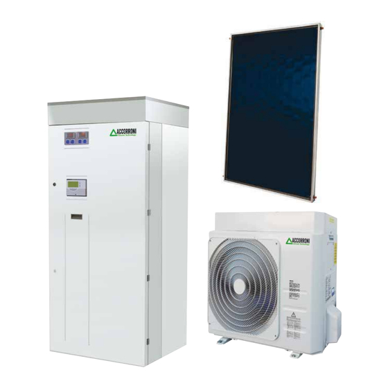
- Page 1 Patented high efficiency heat pump system with direct refrigerant / water exchange to produce domestic hot water and heating for medium users with or without solar thermal integration HUB RADIATOR PLUS HUB RADIATOR PLUS SOLAR...
-
Page 2: Table Of Contents
HUB RADIATOR PLUS 250 - 400 SOLAR ..............................9 4.1 Internal unit dimensions and technical characteristics HUB RADIATOR PLUS / PLUS SOLAR............4.2 Dimensions and technical characteristics of outdoor units HUB RADIATOR PLUS / PLUS SOLAR............ 4.3 Indoor unit HUB RADIATOR PLUS / PLUS SOLAR..........................10 4.4 Booster 3.0 outdoor unit performance characteristics.......................... - Page 3 9.5 Solar station dimensions UNIT 2 PLUS..............................36 9.5 Fixing holes on the rear bracket................................36 10 SECTION E - SOLAR CONTROL UNIT CONTROL MULTI 06 S - HUB RADIATOR PLUS 250 - 400 SOLAR........37 10.1 Generality........................................ 37 10.2 Description of the commands................................. 37 10.3 Technical features....................................
-
Page 4: Main Features
73/23 / EEC, 89/336 / EEC, as amended by directive 93/68 / EEC. 1.6 FIELD OF USE The indoor unit of the HUB RADIATOR PLUS / PLUS SOLAR system The appliances designed and manufactured for heating water in has been designed to be installed only and exclusively inside buildings... -
Page 5: Connexions U.e. / U.i
Firmly fix the copper pipe with a nut of the size indicated in table 3. 2.1 GENERAL PROVISIONS 1) The HUB RADIATOR PLUS / PLUS SOLAR system is E) Securing the connection (Fig. 4) designed to work exclusively with the indoor unit positioned Align the pipes. -
Page 6: Installation Within 5 Meters
Table 4 - Admissible distances U.I. - U.E. (C) MAXIMUM PIPE LENGTH (D) MAXIMUM DIFFERENCE IN HEIGHT (between U.E and U.I.) Models HR 3.0 HR 7.8 HR 9.0 INV (E) ADDITIONAL REFRIGERANT AMOUNT (over 5 m) Maximum length allowed configuration the effective length of the pipes is 6 m horizontally without adding refrigerant and 4 m vertically, in total 10 m. -
Page 7: Outdoor Unit Installation
- Position the air outlet so that the flow is not hindered in any 3. OUTDOOR UNIT INSTALLATION way. In the case of strong wind, make sure that the fan works 3.1 GENERAL INDICATIONS correctly, positioning the unit longitudinally, along a wall or When choosing the installation position, carefully observe the using a shield. -
Page 8: Roof Installation
The outdoor unit is supplied with a charge of R410A refrigerant 3.3 ROOF INSTALLATION - If the outdoor unit is installed on a roof, be sure to level the gas suitable for ensuring proper operation up to a maximum unit. Make sure that the roof structure is appropriate for distance of 5 meters from the indoor unit. -
Page 9: Hub Radiator Plus 250 - 400 Solar
4. SECTION A - INDOOR UNIT / OUTDOOR UNIT TECHNICAL AND CONSTRUCTION FEATURES HUB RADIATOR PLUS 250 - 400 SOLAR 4.1 DIMENSIONS AND TECHNICAL CHARACTERISTICS OF THE INDOOR UNIT HUB RADIATOR PLUS / PLUS SOLAR High temperature system return (M 1”) Low temperature system delivery (M 1”) Domestic hot water delivery (M 1/2”) -
Page 10: Indoor Unit Hub Radiator Plus / Plus Solar
Water mains inlet (M 1/2 ”) 4.3 INDOOR UNIT HUB RADIATOR PLUS / PLUS SOLAR Booster gas line HR refrigeration circuit 1 Main components (5/8” Booster 7.8 / 9.0 - 3/8” Booster 3.0) High temperature system return (M 1”) 10 Liquid line Booster HR refrigerant circuit 1 Low temperature system delivery (M 1”) -
Page 11: Booster 3.0 Outdoor Unit Performance Characteristics
4.4 PERFORMANCE CHARACTERISTICS OF THE OUTDOOR UNIT BOOSTER HR 3.0 BOOSTER HR 3.0 - THERMAL POWER DELIVERED Thermal power delivered kW Heating water delivery temperature °C Ta (°C) - 10 1,96 1,93 1,88 1,80 1,67 1,51 2,.02 1,99 1,94 1,86 1,74 1,58 2,08... -
Page 12: Booster 7.8 Outdoor Unit Performance Characteristics
4.5 PERFORMANCE CHARACTERISTICS OF THE OUTDOOR UNIT BOOSTER HR 7.8 BOOSTER HR 7.8 - THERMAL POWER DELIVERED Thermal power delivered kW Heating water delivery temperature °C Ta (°C) - 10 5,12 5,05 4,91 4,69 4,36 3,93 5,27 5,20 5,07 4,86 4,55 4,13 5,43... -
Page 13: Booster 9.0 Inverter Outdoor Unit Performance Characteristics
4.6 PERFORMANCE CHARACTERISTICS OF THE OUTDOOR UNIT BOOSTER HR 9.0 INVERTER BOOSTER HR 9.0 INV. - THERMAL POWER DELIVERED Thermal power delivered kW Heating water delivery temperature °C Ta (°C) - 10 5,84 5,81 5,79 5,71 5,47 4,98 6,23 6,19 6,17 6,08 5,82... -
Page 14: Technical Data Table Booster Hub Radiator Plus / Plus Solar
4.7 TECHNICAL DATA TABLE BOOSTER HUB RADIATOR PLUS / PLUS SOLAR DESCRIPTION U.M. HR 7.8 HR 9.0 INVERTER HR 3.0 Thermal power (1) 3,11 8,12 3,54 / 8,01 / 8,81* 1,96 Absorbed power (1) 0,74 1,89 C.O.P. (1) 4,20 4,14... -
Page 15: Dhw Withdrawal Table Hub Radiator Plus / Plus Solar 400
HP recovery time+resistance from 38 ° C to 62 °C - External temp. 7 °C* Recovery time from 10 °C to 55 °C - Outdoor temp. 7 °C* *Data calculated with the heating system off 4.10 ACCUMULATION UNIT TECHNICAL DATA TABLE HUB RADIATOR PLUS / PLUS SOLAR DESCRIPTION U.M. - Page 16 CONDENSATE ANTIFREEZE HEATING CABLE WITH ANCHORING BRACKET FOR INCLINED ROOF FOR THERMAL SENSOR, FACTORY FITTED EXTERNAL BOOSTERS MOD. HR 3.0 - 7.8 - 9.0 INCLUDING RUBBER ANTIVIBRATION FLOOR SUPPORT COMPLETE WITH AUXILIARY BASIN EQUIPPED WITH 90 W HEATING CABLE ANCHORING SHELF FOR EXTERNAL BOOSTER RUBBER ANTIVIBRATION MOUNTS INCLUDED FACTORY MADE HYBRID SYSTEM ELECTRONIC...
-
Page 17: Section Bdigital Control Unit Hub Radiator Plus 250 - 400 Solar
5 - SECTION B DIGITAL CONTROL UNIT HUB RADIATOR PLUS 250 - 400 SOLAR DIGITAL CONTROL UNIT Flashing on if the entrance digital flow switch is active (both with pump ON and with pump OFF) On if at least one of the 2 water pumps... -
Page 18: Access To Parameters
___________________________________________________ Regarding the use of the remote terminal (indications on the FUNCTION display and meaning of the keys) do reference to the preceding paragraphs In air / air units, in case of terminal use remote Pressure and release: equipped with NTC probe (VICXS610), from main view allows the display of the configuring par. -
Page 19: Main Alarms
5.6 MAIN ALARMS Cod. Meaning Cause Action Reset Probe alarm Probe faulty Activate open output Automatic or resistive value collector / alarm relay if the value is within out of range Activate buzzer the expected range Flashing icon generic alarm Code on display Probe alarm Probe faulty... - Page 20 5.7 TABLE OF TROUBLESHOOTING CAUSES Alarm Failure Meaning Cause Remedy code Probe technical water 1) Probe interrupted 1) Technical water probe replacement alarm PB1 Probe 2) Probe shorted 2) Control unit replacement 3) Control unit faulty Probe External 1) Probe interrupted 1) External probe replacement alarm PB2 temperature...
-
Page 21: Parameter Tables
31. Tabella Parametri 6. PARAMETER TABLES SUBMENU SELECTION 6.1 SUBMENU SELECTION LABEL MEANING Visualizza tutti i parametri Visualizza solo i parametri di termoregolazione ST10 Funzione unità chiller senza accumulo 0= disabilitata Visualizza solo i parametri di configurazione 1= abilitata ST11 Set point minima temperatura acqua in uscita unità... - Page 22 CF22 Valore di pressione a 4mA / 0,5V 50.0 12 = Allarme termica pompa acqua evaporatore / termica ventilatore di mandata CF23 Valore di pressione a 20mA / 5V 50.0 13= Allarme termica pompa acqua condensatore 14= Flussostato condensatore 15= Disabilitato CF24 Offset PB1 -12.0...
- Page 23 CF44 Default visualizzazione display superiore terminale remoto CO06 Ritardo ON compressore dalla partenza pompa / ventilatore 0 = PB1 di mandata 1 = PB2 CO07 Ritardo OFF pompa / ventilatore di mandata dallo 2 = Niente spegnimento compressore 3 = PB4 CO08 Rotazione compressori 4 = Setpoint reale unità...
- Page 24 FA09 Massima velocità ventole in estate Ar18 Regolazione pompa acqua evaporatore / resistenze antigelo in OFF-stand-by FA10 Set temperatura / pressione minima velocità ventole in -50.0 °C estate °F 0= Disattivata 1= Attivata 50.0 2= Regolazione pompa acqua / resistenze antigelo su sonda PB4 configurata come sonda ambiente FA11 Set temperatura / pressione massima velocità...
-
Page 25: Digital Control Unit Wiring Diagram
dF18 Valvola 4 vie di inversione ciclo AL15 Differenziale bassa temperatura / pressione 25.0 °C 0= ON in cooling °F 1= ON in heating 50.0 dF19 Set temperatura / pressione forzatura ciclo di sbrinamento -50.0 °C °F AL16 Numero massimo interventi ora allarme bassa pressione 50.0 ingresso analogico AL17... -
Page 26: 7/8. Section C - Flat Solar Collectors Hub Radiator Plus 250 - 400 Solar
7/8 - SECTION C FLAT SOLAR COLLECTORS SELECTIVE H+ - HX+ HUB RADIATOR PLUS 250 - 400 SOLAR FLAT SOLAR COLLECTORSSELECTIVE H+ - HX+ APPROPRIATE USE OF THE APPLIANCE The device was built on the basis of the current level of technology and recognized technical safety rules. - Page 27 which certifies that the work has been carried out in a workmanlike TECHNICAL DATA PLATE manner, in accordance with the rules and regulations in force. The technical data plate is placed on the side wall of the Incorrect installation can cause damage to people, animals and appliance.
-
Page 28: Technical Data Table For Flat Solar Collector Selective
MAXIMUM SNOW AND WIND LOAD TECHNICAL FEATURES The collectors have been tested at 2400 Pa This flat solar collector is at the forefront of the market for quality and yield, and also for the use of low environmental impact TRANSPORT AND HANDLING materials. -
Page 29: Hydraulic Circuit
DISTANCES “D” The minimum recommended distance “D” between two rows of collectors installed on a raised frame depends on the latitude of the place and therefore also on the mounting inclination. The distances refer to an annual use of the collector. Total dimensions 7600 mm INCLINATION MINIMUM DISTANCE - ANNUAL USE... -
Page 30: Instructions For The Installer
With an inclination of the roof greater than 45 ° it is necessary to 8. INSTRUCTIONS FOR THE INSTALLER create special workstations. GENERAL WARNINGS Any modification to the products (Panel, Frame, Kettle, FALL PROTECTION WALL Fittings, etc.) is not allowed. The manufacturer assumes no A further possibility of protection for works on sloping roofs (up to liability of any kind for modified products. -
Page 31: Examples Of Connections For Forced Circulation
to people, animals and things, for which the manufacturer cannot be held responsible. Before filling the solar circuit, provide a PACKAGING pressure reducer if the network pressure exceeds 6 bar. The solar collectors are supplied assembled and accompanied by the ordered assembly kit (inclined or raised roof). After removing the appliance from the packaging, make sure that the supply is complete and undamaged. -
Page 32: Probe Installation (Forced Circulation)
PARALLEL CONNECTION (Other examples) For correct insertion of the probe carry out the following operations: - Locate the probe holder well in the panel fittings kit - Insert the sensitive element of the probe in the relative well probe holder The components with the same letter must have the same length, the number of collectors in each series must be the same as the other series in the parallel... -
Page 33: Commissioning Of The Forced Circulation System
8.4 COMMISSIONING OF THE FORCED CIRCULATION SYSTEM - Place the circulation group near the solar tank e higher than the exchanger to avoid air in the circuit. - Connect the PUMP hand pump in point 2, for allow the air to escape into the circuit itself. -
Page 34: Forced Circulation System Inspection And Maintenance
8.6 SYSTEM INSPECTION AND MAINTENANCE FORCED CIRCULATION The solar collector does not require particular maintenance, it is Failed inspections and maintenance can cause damage to the essential to carry out a periodic visual check of the collector itself system and to people, animals or things for which the (cleaning or absence of damage or breakages) and a check of manufacturer cannot be held responsible. -
Page 35: Section Dsolar Station Unit 2 Plus Hub Radiator Plus 250 - 400 Solar
9 - SECTION D SOLAR STATION UNIT 2 PLUS HUB RADIATOR PLUS 250 - 400 SOLAR 9.1 MAIN PARTS OF THE COMBINED CIRCULATION GROUP FOR SYSTEMS SOLARI UNIT 2 PLUS Round trip system 1 Ball valve on the delivery branch (Thermometer with red ring and scale 0-120 °C) -
Page 36: Insulation Box In Epp Unit 2 Plus
9.3 EPP INSULATION BOX UNIT 2 PLUS 9.5 SOLAR STATION DIMENSIONS UNIT 2 PLUS - Dimensions 277x425x150 mm - Side opening on the base for the safety group - Internal joints for housing the 22 mm tube - A special opening allows you to read and adjust the flow rate without removing the cover - Rear fixing bracket 277 mm... -
Page 37: Section E - Solar Control Unit Control Multi 06 S - Hub Radiator Plus 250 - 400 Solar
10 - SECTION E SOLAR CONTROL UNIT CONTROL MULTI 06 S HUB RADIATOR PLUS 250 - 400 SOLAR Output relay contacts capacity: SOLAR CONTROL UNIT CONTROL MULTI 06 S OUT1 - OUT2 - OUT3 - OUT4: 4x2(1)A max 230V~(SPST) voltage free contacts 10.1 GENERAL... -
Page 38: Start
probes probes with range -50 ° C .. + 110 ° C can be used (probes in fig. 10, there is an example of the closing of the control unit supplied with blue cable). WARNING! When closing the control unit, make sure that the If systems with 2 solar panels are created, the probes removable terminal blocks have been inserted correctly (the corresponding to S1 and S4 must be exclusively with a range of... -
Page 39: Installer Parameters
The conditions that cause the WEST manifold pump to WARNING! activate are as follows: In "installer parameters" mode all the outputs are disabled. All S_4≥TABC+Hysteresis value the default values i ndicated are to be considered indicative as they may vary according to the version and without notice. S_4≥S_2+Hysteresis value The following are the conditions that cause the collector pump PRESS KEY ‘... - Page 40 WARNING! the icon is flashing “ ”. Entering parameter P1, the control unit resets the The control is not active with the control unit in the “OFF” state maximum temperatures (TM) recorded up to that moment. (the display shows the word OFF). By exiting this parameter, the control unit resets the temperature display on probe S_1.
- Page 41 Scheme 17 Scheme 5 Natural circulation solar heating system with 1 tank and EAST / WEST solar heating system, 1 tank, direct direct integration via valve logic. integration via valve logic. Control logic Control logic Scheme 06 Scheme 18 Solar heating system with 2 tanks, valve logic control, Solar heating system with 2 tanks, valve logic, integration excluded.
- Page 42 The adjustment fields relating to each single data are listed WARNING! below. It is not possible to set the Hysteresis (HY) to a value higher than that of the relative Differential (ΔT), since the value WARNING! The display of the thermal data to be set contextual to of the Hysteresis is bound to the value of the Differential the selected scheme, i.e.
- Page 43 SELECTED THE PARAMETER P3 How the integration works PRESS KEY ‘ 8 ’ Adjustment range Data Default n0r .. ECO IT IS POSSIBLE TO SCROLL CYCLICALLY THROUGH THE WARNING! DATA ANTIFREEZE USING THE ARROWS ‘’ or ‘’ - The MOD parameter is only visible if one has been set - Antifreeze temperatures ‘TAF’...
- Page 44 P5: RELAY LOGIC SELECTION P7: TEST CONNECTED LOADS Through this parameter it is possible to invert the control logic Through this parameter it is possible to carry out the functional test of of the relays, or to transform the output from Normally Open the loads connected to the control unit.
- Page 45 PRESS KEY ‘ 8 ’ TO CONFIRM THE SETTING MADE Temperature differential of Recooling TR OR PRESS THE 'esc' KEY TO CANCEL THE CHANGE Adjustment range Data Default ΔTR 6 °C .. 15 °C 8 °C Activation / Deactivation of function Recooling System flow rate expressed in liters / minute Adjustment range Data...
- Page 46 Unit of measure P14: COLLECTOR RESET TEMPERATURE With this parameter it is possible to set the temperature value ('T_SE' Adjustment range Data Default - 'T_SW') for resetting the collector pump if the TS_2 safety UNIT °C .. °C °C temperature has intervened, in order to avoid thermal shocks and air pockets in the system.
-
Page 47: Management Of Anomalies Probable Causes
SET THE DATA RELATING TO EACH SINGLE PRESS KEY ‘ 8 ’ THE TEMPERATURE RECORDED SO PARAMETER AS SHOWN BELOW FAR IS RESET; PRESSING INSTEAD 'Esc' YOU RETURN TO THE DISPLAY OF THE STORED TEMPERATURE PRESS THE 'esc' KEY TO RETURN TO THE USER PARAMETERS SECTION PRESS THE 'esc' KEY TO EXIT THE MAXIMUM WAIT 20 SECONDS OR PRESS THE 'esc' KEY TO EXIT... -
Page 48: Section Fwiring Diagrams Hub Radiator Plus 250 - 400 Solar
11 - SECTION F WIRING DIAGRAMS HUB RADIATOR PLUS 250 - 400 SOLAR 11.1 KEY OF ELECTRICAL DIAGRAMS HUB RADIATOR PLUS 250 - 400 SOLAR LEGEND Cr (1) VD (2) terminal block Booster 1 terminal block Booster 2 technical water probe... -
Page 49: (Only One Direct Circulation Group)
11.2 Wiring diagram HUB RADIATOR PLUS SOLAR 250 with double external Booster model 7.8 (only one direct circulation unit) -
Page 50: Wiring Diagram Hub Radiator Plus Solar 250 With Double Outdoor Booster Model 7.8 + 3.0 (Only One Direct Circulation Group)
11.3 Wiring diagram HUB RADIATOR PLUS SOLAR 250 with double external Booster model 7.8 + 3.0 (only one direct circulation group) -
Page 51: Wiring Diagram Hub Radiator Plus Solar 250 With Double Outdoor Booster Model 7.8 (Only One Direct Circulation Group And One Mixed)
11.4 Wiring diagram HUB RADIATOR PLUS SOLAR 250 with double external booster model 7.8 (one direct and one mixed circulation group) -
Page 52: Wiring Diagram Hub Radiator Plus Solar 250 With Double Outdoor Booster Model 7.8 + 3.0 (Only One Direct Circulation Group And One Mixed)
11.5 Wiring diagram HUB RADIATOR PLUS SOLAR 250 with double external Booster model 7.8 + 3.0 (one direct and one mixed circulation group) -
Page 53: (Only One Circulation Group)
11.6 Wiring diagram HUB RADIATOR PLUS SOLAR 250 with external Booster model 7.8 (only one circulation group) -
Page 54: (Only One Circulation Group)
11.7 Wiring diagram HUB RADIATOR PLUS SOLAR 250 with external Booster model 3.0 (only one circulation group) -
Page 55: (Only One Circulation Group)
11.8 Wiring diagram HUB RADIATOR PLUS SOLAR 250 with single external Booster model 9.0 inverter (only one circulation group) -
Page 56: Wiring Diagram Hub Radiator Plus Solar 250 With Outdoor Booster Model 9.0 Inverter (Only One Direct Circulation Group And One Mixed)
11.9 Wiring diagram HUB RADIATOR PLUS SOLAR 250 with single external Booster model 9.0 inverter (one direct and one mixed circulation group) -
Page 57: Section G - Hydraulic Diagrams - Hub Radiator Plus 250 - 400 Solar
HYDRAULIC DIAGRAMS HUB RADIATOR PLUS 250 - 400 SOLAR 12.1 Application example HUB RADIATOR PLUS SOLAR 250 with double external Booster mod. 7.8 Winter air conditioning and DHW production system consisting of an indoor unit HUB RADIATOR PLUS SOLAR 250 equipped with a double inverter circulator, to serve n. -
Page 58: Application Example Hub Radiator Plus Solar 250 With Single Outdoor Booster 9.0 Inverter
12.2 Application example HUB RADIATOR PLUS SOLAR 250 with single external Booster mod. 9.0 inverter Winter air conditioning and DHW production system consisting of an indoor unit HUB RADIATOR PLUS SOLAR 250 equipped with an inverter circulator, to serve n. 1 high temperature hydronic circuit. - Page 59 Address: 60027 Osimo (AN) - Via D’Ancona, 37 Tel 071/723991 - Fax 071/7133153 Appliances: Hub Radiator Mini, Hub Radiator Plus, Hub Radiator Full, Hub Radiator AP, Super Hub Radiator, Hub Radiator Black DECLARES than the product complies with the European Directive 2004/108 / EC Compatibility electromagnetic;...
- Page 60 A2B Accorroni E.G. s.r.l. Via d’Ancona, 37 - 60027 Osimo (An) - Tel. 071.723991 web site: www.accorroni.it - e-mail: a2b@accorroni.it...
Need help?
Do you have a question about the HUB RADIATOR PLUS and is the answer not in the manual?
Questions and answers