
Summary of Contents for Behncke UV matic A20
- Page 1 Installation and Operating Instructions UV systems UV matic A 20 / A 25 / A 35 / A 48 Technical specifications subject to change without notice. Last updated 12/2016.
- Page 2 1.1.1. UMEX GmbH Alkersleber Weg 151 a D-99334 KIRCHHEIM Phone: + 49 036200 641 0 Fax: + 49 036200 641 20 E-Mail: info@umex-gmbh.de Internet: www.umex-gmbh.de, www.abox-uv.de Author: UMEX GmbH Version: 01_2016 Datum: 07.01.2016 1.1.2. ABOX® is a registered trademark of UMEX GmbH, with headquarters in Kirchheim, Germany and protected as a trademark.
-
Page 3: Table Of Contents
1.1.3 Table of contents Introduction Commissioning 1.1.1. Communication 9.1.1. Reactor 1.1.2. General information 9.1.2. Switch cabinet and system 1.1.3. Table of contents 9.1.3. Power cable connection 1.1.4. Liability and warranty 9.1.4. Troubleshooting 1.1.5. General and residual risk 1.1.6. Information about this Maintenance and service User Manual 10.1.1. -
Page 4: Liability And Warranty
1.1.4. Liability and warranty For warranty claims, we are liable only to the extent permitted by the law or according to the terms of the warranty given in agreements as concluded. Other matters are governed by the General Terms & Conditions of your partners, suppliers or UMEX GmbH. We draw your attention to the fact that the warranty is voided by damage resulting from: –... -
Page 5: Explanation Of Symbols
2.1.1 Explanation of symbols Notice General information. Warning Important information or prohibitions to avoid causing damage. Warning Warns the user about dangerous electrical voltage. This sign is used for activities involving system components carrying live current. Warning: UVC radiation If your eyes are not protected, looking at UVC for only a few seconds (and at a distance of several metres) is enough to cause a painful inflammation, similar to the “arc eye”... -
Page 6: Safety Instructions
Safety The installation, commissioning, operation and maintenance of the UV system must be performed by trained and authorised personnel at all times. These appropriately qualified personnel must have read and understood the relevant sections of this Manual, and the safety-relevant sections in particular. If in any doubt, please contact your specialist dealer or the head office of the manufacturer UMEX GmbH. -
Page 7: Hazardous Situations And Safety Instructions
2.1.4 Hazardous situations and safety instructions Situation Subsystem Hazard Action to take Installation/removal UV reactor Burn injury Take the UV system of UV emitter or UV emitters become offline and secure the immersion tube very hot during use. master switch to prevent Laceration injury accidental switch-on. -
Page 8: Work On The Electrical Subsystem
2.1.5 Work on the electrical subsystem For all work on the machine’s electrical subsystem, the following safety precautions MUST be observed/followed at all times: Warning! The voltage used to operate the machine can be dangerous device The system must only be opened by trained technical specialists Isolate the machine before opening the switch box Read the User Manual before opening the machine 3. -
Page 9: Product And Method
4. Product and method terminology Term Explanation UV system The UV system is the complete system, consisting of the UV reactor, the switch cabinet and the ancillary equipment. UV reactor Core component in a UV system, consisting of a reactor housing plus reactor chamber, UV emitters, immersion tubes and UV sensors with various screw fittings. - Page 10 5. Technical data Manufacturer : UMEX GmbH, D-Kirchheim, www.umex-gmbh.de Type : UV-matic A, exclusive mark for BEHNCKE Reactor : Stainless steel, 1.4571 (316) bath-pickled and electric-polished Life time of lamps : 8.000 h in continuous operation : UV-matic A 20 and A 25 = 1 - 35 °C Water temperature UV-matic A 35 and A 48 = 2 - 55 °C...
-
Page 11: Design And Conformity
5.1.1. Life of the main modules / resources Equipment Intervals Testing and inspection Max. Life life maintenance UV lamp 8,000 h 8,000 -10 000h Quartz immersion tube R, T 8,000 h 48 months * Gasket Set P, T 8,000 h 12 months UV sensor P, T... -
Page 12: System Description
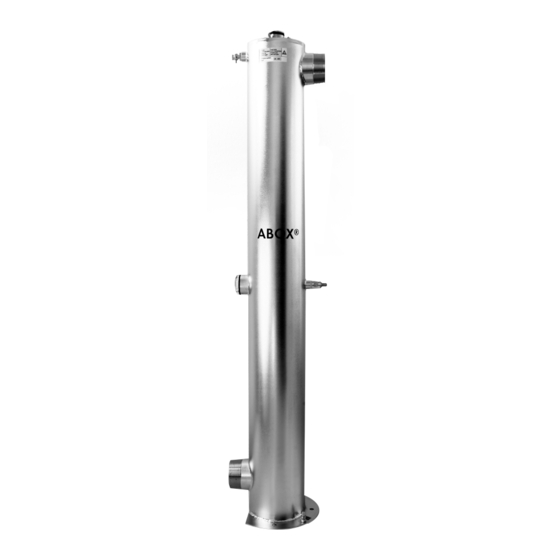
7. System description The UV system consists essentially of a UV reactor and the corresponding switch cabinet. The UV system is delivered ready for installation. Connection cables for the UV emitter and UV sensor are included in delivery. 7.1.1. UV reactor Protective cap Screw joist Bleed valve... - Page 13 7.1.2. Switchbox the series UV matic The UV system switch cabinets are designed for automated operation. All UV systems have been given a 100% factory test prior to shipping. The switch boxes, modules and terminal blocks have been tested against the applicable standards. Complete control unit...
-
Page 14: Controller Overview
7.1.3. Controller overview power sensor menu lamp / current accessory current language cable 60-200 max. SiC-sensor German HG 60/4 / 0,67 A type 1 - 60W 1,0 A* SUV13.1A English HG 80/4 / 0,80 A type 2 - 80W Russian HGA 120/4 / 1,5 A type 3 - 120W HGA 200/4 / 2,0 A... -
Page 15: Menu Navigation
7.1.4. Menu navigation With the first installation all menu options are served and adjusted. Everyone turns out before the distribution is examined and adjusted as follows. Standard setting: 1 = Language German 5 = Half 2 = 1 6 = 50% 3 = 0 7 = 110% 4 = 8.000... -
Page 16: Switching Output
7.1.5. Switching output The switchbox is IP 65 conformal. Around degree of protection to ensuring, a lacquer protection is appropriate at the lower screw of the back. Attaching the reporting exits may take place only from an experienced specialist around the operability and ensure the tightness of the switchbox. -
Page 17: Operation Of The Uv-Device
7.1.6. Operation of the UV-device The UV systems uv matic 25 is for water temperatures 2-35 °C and the UV systems uv matic 35 maximum 55 °C designed for continuous operation. In addition, a continuous water flow at the specified rate is required for optimal operation. -
Page 18: Installation
Installation The installation and commissioning of the System should only be undertaken by trained specialists. Handling glass and UV-RADIATION requires special care. If you are in doubt, please contact us. All contact details are on the first page. The opening and installation of the device is only permitted when there is no water pressure and no connection to electrical power. -
Page 19: Reactor
8.1.1. Requirements for installing the UV system at the customer 8.1.2. Reactor Action to take Purpose Installation indoors Avoids damage to the system Frost-free operation, protection against direct solar radiation Inspection of installation for System check machine/method integration Check the working pressure, ambient Protects the UV system temperature and supply voltage Ensure that sufficient clearance is available... - Page 20 9. Introduction Warning Important information or prohibitions to avoid causing damage. Warning Warns the user about dangerous electrical voltage. This sign is used for activities involving system components carrying live current. Warning: UVC radiation If your eyes are not protected, looking at UVC for only a few seconds (and at a distance of several metres) is enough to cause a painful inflammation, similar to the “arc eye”...
- Page 21 9.1.4. Trouble Shooting Advice Error Error diagnostics Switching position on, - Missing mains voltage LEDs are not illuminated - Safety devices are defective UV lamp does not ignite - Lamp ballast and/or lamp not correctly installed - Contact errors - UV lamp defective - Electronic ballast defective UV intensity too small - UV transmission of the water inadequate...
- Page 22 Required tools, ancillary and safety equipment Tool Ancillary equipment Safety equipment Acid-resistant tools Cleaning fluid Gloves Screwdriver Kitchen roll or cotton Safety goggles Allen key cloths Pers. protective equipment Open-ended spanner 8, 17 Acid-resistant cleaning Box spanner 8 container Adjustable/pump spanner Alcohol for lamp glass 10.1.2.
- Page 23 10.1.3. Inspecting the quartz immersion tube Heat from the emitters and reactions from water constituents can cause deposition to occur on the surface of the quartz glass. These deposits mostly consists of mineral particles, biofilms and other residues generated by algae and bacteria. The deposits cause the surface of the glass to cloud over, meaning that the required dose of UV light can no longer penetrate into the water.
- Page 24 10.1.5. Exchange control UV sensor After 8,000 hours of operation or with UV lamps or AC reactor cleaning The UV sensor change due to interruption of operations 1. Device power off 2. Shut off the pipeline inlet and outlet 3. Make UC system depressurized 4.
- Page 25 Cleaning the irradiation chamber The mechanical or chemical cleaning processes always in the off state of the UV system perform. The cleaning of the reactor interior space is carried out manually. The UV system is suitable for CIP briefly up to 90 ° C. For cleaning, we recommend a flow rate of 2m / s. A sterilization time of 10-30 minutes with saturated steam at a pressure of 2.5 to 4 bar is optimal.
- Page 26 APPLICATION ® CARELA UV CLEAR is a concentrate which is diluted 1:4 with water always at a reaction time of 10-15 minutes is used. In terms of application, several options are available: dipping method The quartz tube is expanded as previously described and in a suitable pan with the 20% solution of detergent treatment.
- Page 27 Spare parts UV matic A 20, A 25, A 35, A 48 Type Ar. No. Description Remark 10064 UV-lamp HG 60/4 W 10080 UV-lamp HG 80/4 W 11120 UV-lamp HGA 120/4 W A20-A35 13100 Quartz tubes 1000 14014 Cap with PG 15000 Header Ø...
- Page 28 14.1.1. Spare parts description Template for use when ordering replacement parts UV Plant type: Device number:...
- Page 29 15. Operating log Date operation activities and controls Result hours remark...
- Page 30 15.1.1 Notes...
- Page 31 16. Conformity EG-Konformitätserklärung EC-Declaration of Conformity CE-Déclaration de conformité Hersteller: UMEX GmbH www.umex-gmbh.de Manufacturer / fabricant: Anschrift: Alkersleber Weg 151 A* D- 99334 Kirchheim Address/addresse: Produktbezeichnung: UV- Desinfektionsanlage Product specification/Description du produit: UV-disinfection plant/Installations de désinfection UV Typen: UV matic A 20 – A 48 Types/types: Seriennummer Siehe Typenschild...
- Page 32 18. Circuit diagram UV-Lamp: HG 60/4 HG 80/4 UV-sensor HGA 120/4 HGA 200/4 SUV13 Grounding reaktor Alarm Enter Mains plug on/off 230±10%VAC Rel 1 Rel 3 Pre fusing: min. 6 A Rel 2 max. 16 A FI-switch 0,03A recommended Correct Alarm threshold UV lamp operation...
Need help?
Do you have a question about the UV matic A20 and is the answer not in the manual?
Questions and answers