Table of Contents
Advertisement
Quick Links
Advertisement
Table of Contents

Summary of Contents for SCHNIER HER 02/01
- Page 1 Operating manual HV supply HER02/02 I t e m n o . : 8 1 0 3 5 3 1 2 0 k V 2 m A...
-
Page 2: Table Of Contents
Contents 1. PRODUCT AND MANUFACTURER .................. 3 1.1. PRODUCT IDENTIFICATION .................... 3 1.2. DESIGNATION ........................3 1.3. WARRANTY ........................3 1.4. MANUFACTURER ......................3 2. GUIDE TO THIS OPERATING MANUAL ................4 2.1. TARGET GROUP ....................... 4 2.2. ACCESSIBILITY TO THE OPERATING MANUAL / STORING ........4 2.1. -
Page 3: Product And Manufacturer
1. Product and Manufacturer 1.1. Product identification This operating manual is part of the device: Device name: High-voltage generator Type: HER 02/01 and HER 02/02 Item number: 810353 1.2. Designation 1.3. Warranty All warranties are void if the device is opened, modified, if parts are not replaced with the original parts or if this operating manual is not observed. -
Page 4: Guide To This Operating Manual
Only with knowledge of this operating manual can errors be avoided and safe, malfunction-free operation be guaranteed. SCHNIER assumes no liability for damage that occurs due to non- compliance with this operating manual! 2.1. -
Page 5: Intended Use
3. Intended Use 3.1. This device is intended for use in stationary electrostatic systems which correspond to the safety requirements of the product standard EN 50348:2010 + Cor.:2010. CAUTION Any start up outside of this condition is prohibited. This device is not a finished part and may only be put into operation after complete and proper installation and if it is detected that the system into which the device will be installed completely corresponds to the regulations of EN 50348. -
Page 6: Further Requirements For The Surrounding System
3.2. Further requirements for the surrounding system The HV generator must only be used in electrostatic systems within a temperature range of 15°C to 50°C and with a relative humidity between 10% and 70% (not condensing). The HV generator is intended for operation in a specific stationary system in an industrial environment. -
Page 7: Installation Instructions
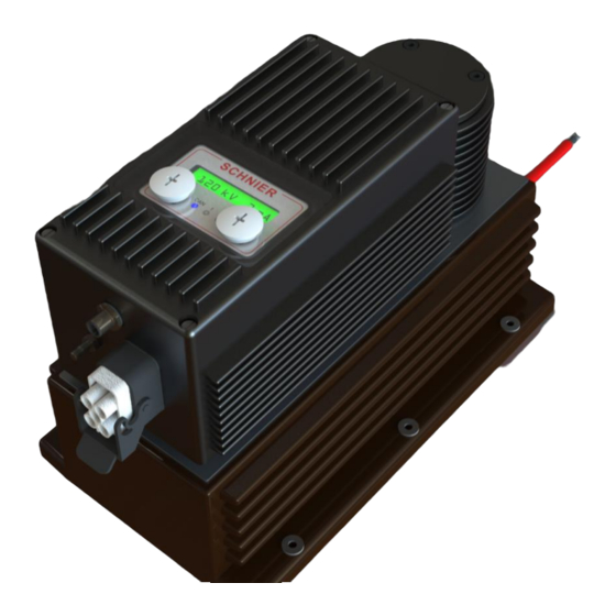
4. Installation instructions 4.1. Structure Figure 3. a 1. Display and keyboard 2. M12 Sensor / actuator plug 5 pin (24V and CAN) 3. POAG pin for ground connection 4. Power connector for power supply + feedback contact 5. Transformer unit 6. -
Page 8: Mounting
4.2. Mounting Fig. 1 The high-voltage generator is intended for wall mounting. So that the cooling ribs can fulfill their function the high-voltage generator must be mounted vertically (as illustrat- ed). The metal housing is fabricated from seawater resistant aluminum and anodized. The brown cascade part is cast from a salt resistant epoxy resin. -
Page 9: Fastening Dimension Sheet
4.3. Fastening dimension sheet Operating manual 810353-BALDE-150220 Version 20.02.2015 Page 9 of 36... -
Page 10: Electrical Installation / Pin Assignments
4.4. Electrical installation / pin assignments Sensor / actuator plug Ground connection POAG Power plug Plug lock 4.4.1. Power plug ILME CQM 04/2 or Harting HAN Q 4/2 Description Signal Power supply L1 400 V Power supply L2 400 V Power supply L3 400 V Not used... - Page 11 The plug connection must meet IP54 at least. The feedback contacts (RM) are designed for 24 V / 1A. They must on- ly be connected to safety extra low voltage systems. To improve the immunity in industrial networks the use of a 4% 2A line choke is recommended in the 400V supply lines.
- Page 12 4.4.3. High Voltage Connection The 4mm high-voltage contact pin of the high-voltage cable must be completely plugged in and the strain relief screw connection must be tightened. CAUTION If shielded HV cable is used, the shielding must be grounded 4.4.4. M12 Sensor / actuator plug (safety extra low voltage) The supply to the controls is done together with the CAN connection via a M12 sensor/...
-
Page 13: Normal Operation
5. Normal operation The specifications for the intended use according to EN 50348 apply. In addition the operating manuals of the relevant electrostatic system must be complied with! Operation of the system must only be carried out by a trained operating team. The per- sonnel must be informed in reasonable intervals about the accident prevention regula- tions and about the operation of the system. -
Page 14: Maintenance And Repair
4. Secure against switching on again. 5. Though the absence of the 400V supply the generators now again report "un- safe". This depends on the system and is OK. 6. For further safety after switching off the 400 V a waiting time of 60 seconds should be implemented up to release of access. -
Page 15: Structure And Function Description
7. Structure and function description 7.1. General Information The high-voltage generator is built in a compact design. The controls, end stage, HV transformer and the HV cascade are combined in one device. The unit is supplied with 3-phase 400 V 50/60 Hz. The controls are separately supplied with 24 V. The power output stage has its own µController, which guarantees a precise and very fast control. -
Page 16: Description Of The Safety Feedback
The software of the power module and the control modules are continually checked and monitored. For errors there is a shutdown and the error output. 7.3. Description of the safety feedback The state of the high-voltage generator is transmitted via the bit "Device is safely off" in the status word (see in document "Explanation of the status word") of a PDO via CAN interface. - Page 17 Control Condition Conditions signal REL 1 1. The bit "High voltage ON" in the control word safe equals 0. 2. The bit "OPEN safety contact" in the control word equals 0. 3. The output voltage is smaller than the safety level that corresponds to the residual energy.
- Page 18 400V supply volt- If the 400V supply voltage is miss- Check supply voltage. If the age. ing or the communication between error continually occurs: the power module and control Check by the manufacturer module is interrupted. required. Safety* If the plausibility test of the safety Check by the manufacturer relay failed required.
- Page 19 The following malfunction messages are not device-related, but rather operation- related and do not lead to the feedback "unsafe". Malfunction messages of the control module (CM) Malfunction Cause Remedy Umin If the output voltage during I-mode Check parameters and if is smaller than the threshold value necessary adapt to the op- in the object directory.
-
Page 20: Block Diagram
7.4. Block diagram Power part with µControl- High voltage High voltage Protective output ler, controller transformer cascade resistance and end stage 24 VDC Current measure- ment Measure- Control module ment with µController CANopen Voltage measurement resistance Front module w/ display, LED*s and buttons 7.5. -
Page 21: Start Up Of The Canopen Interface
8. Start up of the CANopen interface ATTENTION The node guarding function in the higher-level control system must be acti- vated. It is necessary to detect interruptions in the communication with the CAN-Master and then to switch off the high voltage. 8.1. - Page 22 Node ID is not available The generator controls waits until a valid Node ID is input with the buttons. The digit can be selected using the left button. By pressing the right button the number of the corresponding digit is incremented by one. Both buttons must be pressed at the same time and held for 1 second to confirm.
- Page 23 Then the baud rate is requested: Baud rate is requested The baud rate can be selected between 125 kbit/s and 50 kbit/s using the left button. The right button is for confirmation. Using the right button the selected baud rate is shown on the display and a confirmation is expected: Selected baud rate After confirmation of the baud rate a bootup message is sent via the CAN interface of...
-
Page 24: Changing The Node Id And/Or Baud Rate
8.2. Changing the Node ID and/or baud rate If XXX equals a number between 1 and 127, it means that a valid Node ID has already been set. If no change is done to the Node ID or baud rate with the buttons, after 5 seconds the bootup message is sent via the CAN interface of the high-voltage genera- tor and the generator is ready. -
Page 25: The Status Word
The data contents in the RXPDO1 contains three objects from the object directory. The three objects are arranged so: Data contents of the RXPDO1 The data contents in the RXPDO2 contain the numbers 1 to 8 on the display: Data contents of the RXPDO2 The data contents in the RXPDO3 contain the numbers 9 to 16 on the display. -
Page 26: Output From Messages And Warnings
The generator supplies 10 kV controlled. However, if the current of 2mA is reached, then it is limited to this value, i.e. if necessary the voltage decreases. The numbers are displayed here in hexadecimal. RXPDO1 for 10 kV and 2 mA in U-mode Example: 20kV, I-mode, 2mA: In I-mode the roles of U target and I target are exchanged with each other. -
Page 27: Acknowledging A Message
The output voltage and the output current in an ideal case fall back to 0. The speed is dependent upon the system capacity. 9.4. Acknowledging a message The malfunction must be acknowledged before the high voltage can be switched back on. -
Page 28: Description Of The Control Bits
9.5. Description of the control bits Byte Status bit Explanations High voltage ON 1: The high voltage should be switched on 0: The high voltage should be switched off Acknowledge malfunction 1: All malfunctions should be acknowledged 0: no action Caution: During malfunction ac- knowledgment the bit "High voltage ON"... -
Page 29: Description Of The Status Bits
9.6. Description of the status bits Byte Bit Status bit Explanations High voltage is ON 1: Output voltage larger than 90% of voltage target value and the power module working. 0: no high voltage Collective malfunction 1: If any individual malfunction oc- curs. - Page 30 Byte Bit Status bit Explanations Electrical arcing warning 1: Electrical arcing detected. 0: Automatically reset if the status word is queried via SYN object. Umax reached during I-mode 1: Output voltage larger than the threshold in object directory. 0: If the output voltage is smaller than the threshold in the object directory.
- Page 31 Byte Bit Status bit Explanations dI/dt switch off 1: Change of the output current larger than the threshold value in the object directory. A single malfunction. 0: If this malfunction does not occur or is acknowledged. The specified error is set so that this switch off is deactivated.
-
Page 32: Settings Via Sdos
Byte Bit Status bit Explanations Switch off Shut down power mod- 1: Output voltage larger than 75 KV. 0: If this malfunction does not occur or is acknowledged. Power module over-voltage warn- 1: 400V supply voltage exceeded by more than 10 %. 0: If this warning does not appear or was acknowledged. -
Page 33: Electronic Description Of The Interface
9.8. Electronic description of the interface A so-called eds file is made available from SCHNIER for programming the higher-level control system. Generally speaking this can read in and contains all format descriptions of the objects in machine-readable form. -
Page 34: Overview Of Control And Status Word
9.9. Overview of control and status word Operating manual 810353-BALDE-150220 Version 20.02.2015 Page 34 of 36... -
Page 35: Object Directory
9.10. Object directory Operating manual 810353-BALDE-150220 Version 20.02.2015 Page 35 of 36... -
Page 36: Declaration Of Conformity
Product designation: High voltage generator Model / generator number Type HER 02/01 810353 and Type HER 02/02 810353/001 We hereby declare, that the above described devices due to their design and construction as well as in the version that we have put into circulation correspond with the EC Directives:...
Need help?
Do you have a question about the HER 02/01 and is the answer not in the manual?
Questions and answers