
Summary of Contents for Greyline Instruments PSL 5.0
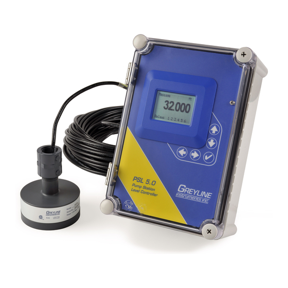
- Page 1 USER'S GUIDE Installation & Operation Instructions Pump Station Level Controller Model PSL 5.0 Manual Series A.1.4...
- Page 2 Note: This page has been left blank intentionally.
-
Page 3: Table Of Contents
PSL 5.0 Pump Station Level Controller INDEX CONNECTIONS: ....................4 KEYPAD SYSTEM...................6 CALIBRATION MENU ..................7 ICONS........................8 MAIN DISPLAY ....................9 MESSAGE ICON ....................9 STATUS ......................9 PASSWORD ....................10 UNITS/MODE ....................11 CALIBRATION ....................12 RELAY PARAMETERS .................14 ... -
Page 4: Connections
PSL 5.0 Pump Station Level Controller CONNECTIONS: POWER INPUT: The standard model requires AC power input between 100 to 240 VAC 50/60Hz . No adjustments are necessary for voltages within this range. Optional DC input model requires 9-32 VDC/9 Watts. Connect to + and - terminals. - Page 5 PSL 5.0 Pump Station Level Controller CONNECTIONS SENSOR CORE SHLD PRESSURE SENSOR SRC SNK + – + – DATA LOGGER OPTION RELAYS RLY3 RLY4 RLY5 RLY6 POWER INPUT – 4-20mA HEATER OPTION RLY2 RLY1 USB HARNESS CONNECTOR Page 5...
-
Page 6: Keypad System
PSL 5.0 Pump Station Level Controller KEYPAD SYSTEM The following diagram shows the PSL 5.0 menu system. Arrows show the four directions to leave a menu box. Pressing a corresponding keypad arrow will move to the next item in the direction shown. -
Page 7: Calibration Menu
PSL 5.0 Pump Station Level Controller CALIBRATION MENU Page 7... -
Page 8: Icons
PSL 5.0 Pump Station Level Controller ICONS Ç Message waiting. Press Data logging Data logging USB file download. File download completed. Download Error. Echo OK. No Echo . Measurement switched to pressure sensor. Page 8... -
Page 9: Main Display
PSL 5.0 Pump Station Level Controller MAIN DISPLAY 29.055 The main display shows the units selected from the Units/Mode menu, Level or Range being measured and RELAY states. Relays 1 2 3 4 5 6 MESSAGE ICON --Message----------- Data log... -
Page 10: Password
PSL 5.0 Pump Station Level Controller PASSWORD --Password---------- Password 0000 The password (a number from 0000 to 9999) prevents unauthorized access to the Calibration menu. From the Main display press the key to get to Password . Factory default password is 0000 and if it has not been changed press the ... -
Page 11: Units/Mode
PSL 5.0 Pump Station Level Controller UNITS/MODE --Units/Mode-------- Mode Level Linear press the and then the or to select Mode Level From Temperature Range Range mode displays distance from the sensor to the target or liquid surface like a tape measure. -
Page 12: Calibration
Distance from sensor to Zero level. Damping Minimum damping allows fast response to level changes. Increasing damping slows the PSL 5.0's response to level changes and is ideal to smooth the display and outputs in turbulent conditions. Damping value is shown in percent (0-99%). Some experimentation may be required to select the optimum damping value. - Page 13 2. Check the maximum range with the sensor installed by: When liquid is at zero level press to view the Range reading in the Status menu. Use this range measured by the PSL 5.0 as the Max Range setting.
-
Page 14: Relay Parameters
PSL 5.0 Pump Station Level Controller RELAY PARAMETERS --Relay Parameters-- Relay Press and or to select a corresponding relay number (6 Function Level Relay Mode Pump relays are standard). 55.000in 40.000in Press or to select... - Page 15 PSL 5.0 Pump Station Level Controller Alternate Up to six pumps/relays can be set to alternate when in pump mode. Following the end of a pump cycle pumps will swap ON and OFF relay settings. PUMP ALTERNATION (R1, R2, R3)
-
Page 16: Data Logging
PSL 5.0 Pump Station Level Controller DATA LOGGING --Data Logging------- Log Site ID Setup Mode Level Range Set Date Feb 18/2008 Select Data Logging from Menu Selections. Mar 19/2009 Set Time 11:27:40 12:28:41 Interval 10sec Log Site ID Enter a number from . - Page 17 PSL 5.0 Pump Station Level Controller Download letter will be A for the first download from an instrument. B for the second, then C etc. At the letter Z a - character will appear indicating that the maximum number of downloads for that instrument are on the USB flash drive.
-
Page 18: Special Functions
PSL 5.0 Pump Station Level Controller SPECIAL FUNCTIONS --Special Functions- Language English Analog Out 4-20mA Language English French Spanish Select Backlight High and press . Reset Relay Log Restore Defaults New Password 0000 Analog Out Select 4-20mA or 0-5V mode for the analog output. -
Page 19: Sensor Mounting/Location
GOOD SENSOR MOUNTING/LOCATION - Tank Level/Inventory Applications 90° Each PSL 5.0 Level Transmitter includes a non- contacting ultrasonic sensor. The sensor must be installed in a position to obtain unobstructed echoes from the liquid or material being measured. Mount the sensor away from pipes, ladders, or structural members which might cause continuous false echoes. -
Page 20: Sensor Mounting Methods
PSL 5.0 Pump Station Level Controller SENSOR MOUNTING METHODS Notes: 1. Use the ¾" NPT "Isolation Coupling" supplied and hand tighten only. Do not clamp sensor FLANGE MOUNT body or stem. FLEXIBLE 2. Locate the sensor 1 ft (30 cm) from... - Page 21 PSL 5.0 Pump Station Level Controller ENCLOSURE INSTALLATION Locate the enclosure within 20 ft (6 m) of the sensor (500 ft -150 m optional). The enclosure can be wall mounted with the four mounting screws (included) or panel mounted with Option PM Panel Mount kit from Greyline Instruments.
-
Page 22: Error/Warning Messages
The PSL 5.0 will hold the display and outputs at the last reading until a new echo is received. If a redundant level sensor is connected the PSL 5.0 will seamlessly switch to the second sensor without an echo loss error message. -
Page 23: Field Troubleshooting
PSL 5.0 Pump Station Level Controller FIELD TROUBLESHOOTING SYMPTOMS CHECK Display - full scale - zero - erratic - random - drifting up - drifting down ECHO LOSS prompt - flashing Calibration Non-Linear SYMPTOMS FAULTS SOLUTIONS Unit “See’s” Wrong Target Due To:... - Page 24 PSL 5.0 Pump Station Level Controller - sensor cable extended and junction not - Use metal Junction Box insulated - through enclosure - use metal enclosure - through 4-20mA output cable - use shielded twisted pair (shielded to AC ground)
- Page 25 PSL 5.0 Pump Station Level Controller PZxx Series Sensors Troubleshooting Resistance measured (between the shield and center wire) across the coaxial cable ends by mulitmeter indicates ambient temperature. Resistance vs. Temperature Page 25...
- Page 26 PSL 5.0 Pump Station Level Controller FUSE REPLACEMENT 1. Turn OFF power. 2. Loosen cover screw and open. 3. Remove power module. 4. Locate fuse on Power Board. 5. Replace fuse with 2 AMP/ 250V, 5 x 20mm fuse. 6. Reinstall power module into chassis.
-
Page 27: Applications Hotline
PSL 5.0 Pump Station Level Controller APPLICATIONS HOTLINE For applications assistance, advice or information on any Greyline Instrument contact your Sales Representative, write to Greyline or phone the Applications Hotline below: United States: Tel: 315-788-9500 Fax: 315-764-0419 Canada: Tel: 613-938-8956... -
Page 28: Product Return Procedure
PSL 5.0 Pump Station Level Controller PRODUCT RETURN PROCEDURE Instruments may be returned to Greyline for service or warranty repair. Obtain an RMA Number from Greyline - Before shipping a product to the factory please contact Greyline by telephone, fax or email to obtain an RMA number (Returned Merchandise Authorization). - Page 29 PSL 5.0 Pump Station Level Controller LIMITED WARRANTY _____________________________________ Greyline Instruments warrants, to the original purchaser, its products to be free from defects in material and workmanship for a period of one year from date of invoice. Greyline will replace or repair, free of charge, any Greyline product if it has been proven to be defective within the warranty period.
-
Page 30: Appendix A - Options
(152m) as required during installation. No adjustment is required when the sensor cable is extended or shortened. Use only RG62AU (or RG62U) coaxial cable which is available from Greyline Instruments or your local distributor. Nominal impedance of RG62AU cable is 93 ohms. - Page 31 PSL 5.0 Pump Station Level Controller EXTENDED SENSOR CABLE INSTALLATION IN MANHOLE MANHOLE COVER XC EXTENDED SENSOR CABLE UP TO 500 ft 152 m CONDUIT TO ELECTRONICS ULTRASONIC SENSOR Wetwell, Sump or Pump Station Page 31...
- Page 32 PSL 5.0 Pump Station Level Controller SENSOR INTRINSIC SAFETY (OPTION ISB) When connected through Intrinsic Safety Barriers, Greyline PZ** Series sensors are certified for installation in a hazardous location rated: Class I, Groups C,D Class II, Groups E,F,G Class III The Intrinsic Safety Barrier may be ordered with the Greyline instrument and is supplied mounted in the Greyline instrument enclosure.
- Page 33 PSL 5.0 Pump Station Level Controller GN3SPEC-ISB-03 The intrinsic safety barrier assemblies installed in the OCF 5.0/SLT 5.0/PSL 5.0 limit the voltage and current supplied to the transducers to the values listed under ‘Barrier Specifications’. To safely install a Greyline...
- Page 34 PSL 5.0 Pump Station Level Controller GN3SPEC-ISB-05 The intrinsic safety barrier assemblies installed in the PSL 5.0 limit the voltage and current supplied to the transducers to the values listed under ‘Barrier Specifications’. To safely install a Greyline transducer certified for use in hazardous...
- Page 35 PSL 5.0 Pump Station Level Controller ENCLOSURE HEATER AND THERMOSTAT - Option TH Instruments can be factory-equipped with an Enclosure Heater and Thermostat or the module can be customer-installed. The Thermostat is factory set to turn ON at 40°F (4.5°C) and OFF at 60°F (15.5°C).
- Page 36 16 to 48" (400 to 1200 mm) away from the end of the sensor. Allow a few seconds for the PSL 5.0 to lock onto the target before displaying its distance. The PSL 5.0 will now display Range in ft or cm (factory calibration).
- Page 37 PSL 5.0 Pump Station Level Controller APPENDIX B - APPLICATIONS BACKGROUND Conditions in the tank or channel where the ultrasonic sensor is installed can affect the performance, range and accuracy of the system. The following notes are for general reference. Contact Greyline Instruments or your local representative for specific information on your application.
-
Page 38: Conversion Guide
PSL 5.0 Pump Station Level Controller CONVERSION GUIDE FROM MULTIPLY BY US GALLONS CUBIC FEET 0.1337 US GALLONS IMPERIAL GALS 0.8327 US GALLONS LITRES 3.785 US GALLONS CUBIC METERS 0.003785 LITRES/SEC 15.85 LITRES CUBIC METERS 0.001 BARRELS US GALLONS BARRELS IMPERIAL GALS 34.9726... -
Page 39: Specifications
PSL 5.0 Pump Station Level Controller 7.4 / 188 mm " SPECIFICATIONS 6.46 / 164 mm " 5.12 / 130 mm " Accuracy: ±0.25% of Range or 2 mm, whichever is greater Repeatability and Linearity: 0.1% F.S., Displays: White, backlit matrix -... - Page 40 PSL 5.0 Pump Station Level Controller Optional PZ34T_F Maximum Range: 32 ft. (10 m) Minimum Range (Deadband): 16" (406.4 mm) Operating Frequency: 46 KHz Beam Angle: 8º Temperature Compensation: Automatic, continuous Operating Temperature: -40° to 150ºF (-40° to 65ºC) Maximum Operating Pressure: 20 psi (1.35 Bar)
- Page 41 PSL 5.0 Pump Station Level Controller Optional Sensor PZ32T 25' (7.6 m) RG62AU 3/4" COAXIAL CABLE Maximum Range: 32 ft. (10 m) ISOLATION COUPLING Deadband (blanking): Programmable, minimum 12” (305 (SUPPLIED) Beam Angle: 8° at 3 DB 3/4" 3-7/8 "...
- Page 42 PSL 5.0 Pump Station Level Controller Optional PZ15 25 ft (7.6 m) RG62AU COAXIAL CABLE (50 ft 15 m OR 100 ft 30 m OPTIONAL Maximum Range: 15 ft (4.57 m) Minimum Range (Deadband): 8" (203.2 mm) 3/4“ NPT Operating Frequency:...
- Page 43 PSL 5.0 Pump Station Level Controller Optional LTB35 Operating Level Range: 0-15 psi (35 ft) / 1.0 bar (10 m) Wetted Materials: 316 stainless steel, Delrin, Viton, PTFE, polyurethane Cable: 40 ft (12 m) polyurethane jacketed, shielded, with vent tube and rated to 200 lb.
-
Page 44: Psl 5.0 Relay Calibration Record
PSL 5.0 Pump Station Level Controller PSL 5.0 RELAY CALIBRATION RECORD Circle Selected Units and Enter Values in the Blank Spaces. RELAY 1 2 3 4 5 6 Low Alarm Function LOS Mode Level Mode Hi Alarm Sen B Fault...
Need help?
Do you have a question about the PSL 5.0 and is the answer not in the manual?
Questions and answers