
Related Manuals for Abra AK-252


Summary of Contents for Abra AK-252
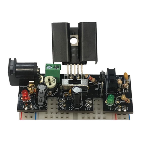
- Page 1 Variable Power Supply Variable Power Supply 1.24VDC - 26VDC Educational 1.24VDC - 26VDC Educational DIY KIT for Breadboard DIY KIT for Breadboard...
-
Page 2: Table Of Contents
Table of Contents Components List ......2 Tools required ........3 Special Features of AK-252 ..... 3 Assembly .......... 4 Let’s Get Start with Soldering ..4 How To Use ........8 Schematic ......... 9 Board Layout ........9... -
Page 3: Components List
Components List Description Abra Part # PCB Board AK-252-BRD MIC2941-Voltage Regulator IC MIC2941ABT 1N5818 Diode 1N5818 1K-Resistors R1/4-1K Resistors: 11K R1/4-11K R1/4-20K 6.2K R1/4-6.2K 2.1mm Power Jack 31-155-0 100K Potentiometer 13P100K Capacitors: 104uf CM104 47uf 47R25 Switch SSW-120-BB 3mm pitch Terminal Block... -
Page 4: Tools Required
Tools required Special Features of AK-252 This Breadboard power supply module is designed to get regulated voltage from any external power source, either from the DC barrel jack or terminal block. The best part of this board is, you can use the power supply at three different modes of voltages- 3.3V,5V and at variable voltages from 1.25V to... -
Page 5: Assembly
Assembly Let’s Get Start with Soldering Follow my step by step instructions below to solder the PCB board. Carefully observe the note points that are provided. Step 1: Start with IC, place as shown. Note: Keep a little up for bending. - Page 6 Step 2: Follow up by 2.1mm power jack. Solder the two types of switches to there respective places. Solder it by placing board to the Three pin switch is on-off switch support as shown and sw2 i.e. bigger switch is an output voltage adjustable switch.
- Page 7 Step 4: For this step solder the potentiometer and diode as indicated in the picture below. Make sure the direction of the diode is same as per the PCB. Note: the silver coting of the diode is the n-side i.e. point your silver side towards the arrow symbol of the diode as shown in figure.
- Page 8 Step 6: Finally, you will solder all resistors and the terminal block. • R1: 1K • R2: 1K • R3: 20K • R4: 11K • R5: 6.2K...
-
Page 9: How To Use
How To Use The Power Supply Provides three different output voltages. The voltage can be set to 3.3V and 5V or it can be adjusted using the potentiometer from 1 to 20V. The Red LED indicates whether the board is getting power or not. -
Page 10: Schematic
Schematic Board Layout...
Need help?
Do you have a question about the AK-252 and is the answer not in the manual?
Questions and answers