Table of Contents
Advertisement
Quick Links
Advertisement
Table of Contents

Subscribe to Our Youtube Channel
Related Manuals for GAS N2-Generator


Summary of Contents for GAS N2-Generator
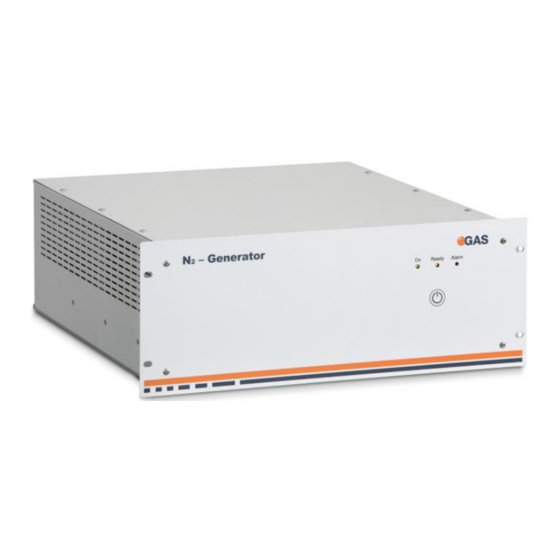
- Page 1 -Generator USER MANUAL G.A.S. Gesellschaft für analytische Sensorsysteme...
- Page 2 -Generator – User Manual Version 1.0.3, February 2021 All data, texts, designs, images and other elements used in this user manual are protected by copyright law. Any infringement may be subject to legal action. Passing it on to third parties and producing copies of any kind or form – on the whole or in parts - is not permitted without written agreement of G.A.S.
-
Page 3: Table Of Contents
Storage and Transport ................. 13 Cleaning and Maintenance ................14 Cleaning ...................... 14 Maintenance ....................14 Description of the N2-Generator unit..............15 Purpose of the device .................. 15 Dimensions ....................15 Overview of the appliance ................16 Installation and operation requirements ............18 Commissioning .................... - Page 4 -Generator – User Manual Operation ......................21 User Interface ....................21 Alarms and Signals..................22 7.2.1 Pre-alarm ....................22 7.2.2 Alarm ....................23 Workflow: Installation of N -Generator ............... 25 Maintenance ...................... 27 -Generator ....................28 Appendix ......................29 10.1 Technical Data N -Generator ..............
-
Page 5: General Information
-Generator – User Manual 1 General Information 1.1 Information about the Manual This manual describes a safe and adequate handling of the device. Following the instructions of the indicated safety aspects and instructions as well as the national and/or local rules and general safety regulations concerning the prevention of accidents are absolutely imperative. -
Page 6: Notation For Dialogs, Elements And References
1.3 Notation for dialogs, elements and references Example Dialog: System › Connections › LAN File Transfer › Settings… › Test Connection Example Elements: Gas Out, Sample gas in Example: References Advanced User Manual, Chapter 5.1 Installation Reguirements... -
Page 7: Scope Of Supply
-Generator – User Manual 1.4 Scope of Supply Assure that you have received the full scope of supply. If there is any part missing, please contact the GAS-hotline immediately. Standard Scope of Supply N2 Generator (1 piece) Power plug (1 piece) - Page 8 -Generator – User Manual User Manual (1 piece) Transport box (1 piece) Transport palett (60 x 80 cm) INFORMATION! It is recommended to keep the transport box for a safety return transport. 8 / 31...
-
Page 9: Liability And Guarantee
-Generator – User Manual 1.5 Liability and Guarantee This user manual describes the safe and proper handling of the device. All data and reference within this manual are compiled under the valid regulations, the state-of-the-art as well as G.A.S. experiences of several years. This user manual must be stored together with and close to the device at any time and accessible to all persons, who operate or handle the device at any time. -
Page 10: Safety
The device and its equipment are not certified for the employment in areas with explosive gas air mixtures. All claims or requirements of any kind against the manufacturer and/or its authorized persons that arise due to damages from a not intended use of the device will be... -
Page 11: Responsibility Of Operator
-Generator – User Manual rejected. All damages that arise from a not intended use are of the operator’s responsibility. The intended use of the equipment and its correct handling according are described in the operating instructions of this manual. Other parts than the parts belonging to the scope of supply, may only be used after G.A.S. -
Page 12: Dangers
-Generator – User Manual 2.4 Dangers The device and its equipment is subject to an endangerment analysis. The construction and execution of the device corresponds to the today's state-of-the-art. The device is reliable in service when operated according to its intended use. DANGER Exercise great care in handling current-carrying parts like the power supply cord. -
Page 13: Packing
• Prevent unauthorized access • Do not store outside • Protect the equipment from moisture and dust • Put protective caps on all gas sockets • Avoid mechanical vibrations • Do not expose the equipment to aggressive substances • Protect the equipment from direct sun light •... -
Page 14: Cleaning And Maintenance
-Generator – User Manual WARNING! Protective caps should be put on gas sockets in case the device is stored or transported. 4 Cleaning and Maintenance Natural aging and the wear of certain components of the equipment require a regular cleaning and maintenance. -
Page 15: Description Of The N2-Generator Unit
G.A.S. measuring devices used typically in positive ion mode. Nitrogen generators replace the use of inconvenient cumbersome high pressure gas cylinders as a source of hydrocarbon-free air. Eliminating the use of gas cylinders allows to reduce annual operating costs. This system is engineered to be easy to install, requires only little annual maintenance and can be used in laboratories and/or light industrial environments. -
Page 16: Overview Of The Appliance
-Generator – User Manual 48 cm 19” 7.1” 18 cm 21.1” 54cm 22” 56 cm with front handles 5.3 Overview of the appliance All connections, electric and air, are made at the back panel. Refer to the figure below. Front view Rear view Description ON/OFF LED START/STOP button... - Page 17 -Generator – User Manual N2 Outlet pressure regulator with gauge Outlet RS485 RS 232 Power switch Power connector Fuse Cooling fan air 17 / 31...
-
Page 18: Installation And Operation Requirements
-Generator – User Manual 5.4 Installation and operation requirements INFORMATION! • The nitrogen generator should be positioned on a flat surface that is not exposed to vibrations and able to withstand a weight greater than 50 kg WARNING! • Do not position the generator near flames or other heat sources •... -
Page 19: Commissioning
-Generator – User Manual work has been completed • The power line should be fitted upstream with a suitable device to protect against short-circuits and earth leakage and isolate the appliance from other equipment • Use cables with double insulation, in accordance with the standards in force in the country concerned •... -
Page 20: Shutting Down
-Generator – User Manual 6.2 Shutting down INFORMATION! List of operations to be performed before powering off the generator at the power switch: • Hold the Start / Stop button to stop the Nitrogen generation • Wait at least 4 minutes •... -
Page 21: Operation
-Generator – User Manual 7 Operation 7.1 User Interface The front panel has three LEDs: GREEN (1), YELLOW (2), RED (3) and START/STOP button (4) Press the START/STOP button (4) to turn ON/OFF the heat oven catalyst. The following table shows the link between LED status and unit status. Status Green LED (1) Yellow LED (2) -
Page 22: Alarms And Signals
-Generator – User Manual 7.2 Alarms and Signals During normal operation the red LED (3) is OFF and the system carries out several automatic checks. In the event of minor anomalies or services request the yellow LED is ON when the red LED flashes to signal a pre-alarm message (the flashes number of red LED identifies the type of founded problem) in these cases the unit does not stop the N2 production. -
Page 23: Alarm
-Generator – User Manual Charging time under the threshold Column discharged pressure too low Service 1 required Service 2 required Service 3 required Internal temperature Zero-Air module error 7.2.2 Alarm When an alarm is activated, the green LED in On steady, the yellow LED is OFF and the red LED comes on in the following sequence: Flashes (to indicate the alarm) –... - Page 24 -Generator – User Manual Tank pressure sensor damage Over pressure Discharge error Memory error Memory damage 24 / 31...
-
Page 25: Workflow: Installation Of N 2 -Generator
(PSA) technology that needs to get rid off the oxigen that typically gets into the gas ways and needs to fully flushed out after a transport or a longer time of the device when being switched off. - Page 26 Allow the generator to idle minutes before connecting any equipment. Up to 48 h purging time is necessary for the initial installation. Connect the output to the device input (Drift gas/Carrier gas adapter) using a 3 mm (Swagelok) tube. 26 / 31...
-
Page 27: Maintenance
-Generator – User Manual 9 Maintenance Natural aging and the wear of certain components of the equipment require regular cleaning and maintenance. With proper care and maintenance, the nitrogen N2- Generator should provide years of trouble-free operation. There are no adjustments to be made to the generator. -
Page 28: N -Generator
-Generator – User Manual INFORMATION! Prior to servicing of the N -Generator, turn off the compressed air and power supplies to the generator, and ensure that the system is de-pressurized. To ensure consistent product performance and reliability only use genuine replacement parts and filter cartridges. 9.1 N -Generator The primary maintenance task required is:... -
Page 29: Appendix
-Generator – User Manual 10 Appendix 10.1 Technical Data N -Generator Model: N -Generator outlet 450 ml/min Flow rate (Max) 1.0 bar (14.5 psi) Outlet pressure (Min) 4 bar (58 psi) Outlet pressure (Max) >99.999% Nitrogen purity <-60°C (-76°F) Outlet Dew-point <... - Page 30 -Generator – User Manual IEC320-C14 Connection type 200W (320 W) Nominal power (Max) 4A (250Vac – T) Fuse rating (5x20mm) 27 kg Net weight Standard 19” Rack 4U-deep 54 cm Dimensions Connections 1/8" female Outlet port Operating conditions 5-35°C (41-95°F) Temperature 80 % at 25°C (77°F) Humidity (max, non condensing)
-
Page 31: Troubleshooting
When generator is switched ON for the first time or after some time in OFF mode it needs some time to generate high quality gas. Wait at least 10 minutes. If this does not solve the problem maybe the moisture traps or the media filter must be exchanged.
Need help?
Do you have a question about the N2-Generator and is the answer not in the manual?
Questions and answers