Table of Contents

Summary of Contents for Jupiter Avionics JA37-001
- Page 1 JA37-001 Aural Message Generator - 3 Channel Installation and Operating Manual Rev. C Jupiter Avionics Corporation 1959 Kirschner Road Kelowna BC Canada V1Y 4N7 Tel: +1 778 478 2232 Toll-Free: 1 855 478 2232 www.jupiteravionics.com...
- Page 2 All rights reserved Jupiter Avionics Corporation (JAC) permits a single copy of this manual to be printed or downloaded for the express use of an installing agency. Any such electronic or printed copy of this manual must contain the complete text of this copyright notice.
-
Page 3: Table Of Contents
JA37-001 Aural Message Generator - 3 Channel Installation and Operating Manual Table of Contents SECTION 1 - DESCRIPTION ............................1 System Overview .............................. 1 Features Overview ............................1 Inputs and Outputs ............................1 1.3.1 Inputs ................................ 1 1.3.2 Outputs ..............................1 Specifications .............................. - Page 4 JA37-001 Aural Message Generator - 3 Channel Installation and Operating Manual Appendix A - Installation Drawings ........................... A1 Introduction ..............................A1 Installation Drawings ............................A1 Appendix B - Certification Documents ........................B1 Airworthiness Approval ........................... B2 ...
-
Page 5: Section 1 - Description
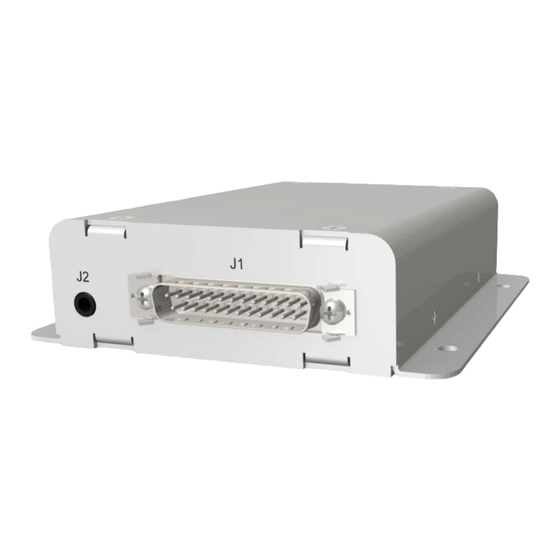
SECTION 1 - DESCRIPTION System Overview The JA37-001 Aural Message Generator - 3 Channel is a dual channel alerting system that provides up to three different messages. The JA37 is setup on a per installation basis using cable CAB-USB-0006, or Configuration Cable JA99-001 and CAB-USB-0002, and downloading the system configuration settings and aural messages into non-volatile devices. -
Page 6: Specifications
JA37-001 Aural Message Generator - 3 Channel Installation and Operating Manual Specifications 1.4.1 Electrical Specifications Power Input Primary nominal voltage 28 Vdc Secondary nominal voltage 14 Vdc Maximum voltage 30.3 Vdc Minimum voltage 11.0 Vdc Emergency voltage 9.0 Vdc Input current 0.5 A max... -
Page 7: Mechanical Specifications
Installation kit part number INST-JA37 1.4.3 Environmental Specifications The JA37-001 Aural Message Generator - 3 Channel has been tested to the environmental conditions listed below. Environmental categories for which TSO compliance has been demonstrated are listed in the Environmental Qualification Form in Appendix B of this manual. -
Page 8: Section 2 - Installation
Introduction This section contains unpacking and inspection procedures, installation information, and post-installation checks. Continued Airworthiness Maintenance of the JA37-001 is on condition only. Scheduled inspection and/or periodic maintenance of this unit is not required. Unpacking and Inspecting Equipment Unpack the equipment carefully. Check for shipping damage and report any problems to the relevant carrier. Confirm that the Authorized Release Certificate or Certificate of Conformance is included. -
Page 9: Cabling And Wiring
2.4.3 Mechanical Installation The JA37-001 can be mounted in any attitude and location with adequate space for the front panel and sufficient clearance for the connector and wiring harness. It requires no direct cooling. 2.4.4 Post Installation Checks 2.4.4.1... -
Page 10: Message Mute Operation
Power On Self-Test Operation When the JA37-001 power is off and then POWER INPUT is applied, the three messages will play in the following order: message 1; message 2; message 3. The Power On Self-Test messages may be muted at any time using the MESSAGE MUTE input. - Page 11 Within ProCS™, the configurable settings for the JA37-001 are grouped together into the following sections: 2.6.2.1 JA37-001 Configurable Pins Function Select Several of the connector pins can be configured to meet the requirements of specific installations. Refer to JA37-001 Interconnect. The message trigger activation can be selected as Active Hi, or Active Lo.
- Page 12 JA37-001 Aural Message Generator - 3 Channel Installation and Operating Manual The message Playback may be selected as 'Continual' or 'One-Shot' for each message (1 through 3). 2.6.2.2 JA37-001 Messages Browse for audio files Play selected audio file Audio Files The JA37-001is loaded with standard audio signals for each of the three messages, but the audio files window allows these signals to be replaced with other recordings during the configuration process.
- Page 13 'Write JA37-001 Messages…'. The window 'Select Messages to Write' (see below) will open, allowing the selected audio file message to be uploaded to the JA37-001. ProCS will automatically convert any WAV file to the required audio sample rate for the JA37-001.
-
Page 14: Other Configuration Features
Selection) are shown in this section. 2.6.3 Other Configuration Features In the JA37-001 Product Information Window, the model number, serial number and check sum of the JA37-001 Aural Message Generator - 3 Channel can be viewed. Installation Kit The kit required to install this unit is not included with the unit. -
Page 15: Section 3 - Operation
Mute Switch/Button If the JA37-001 is playing Alert messages (either because an alert input is active or when Power On Self-Test is occurring), momentary activation of the remote Message Mute switch or button stops all messages from playing until the next message is triggered. -
Page 16: Appendix A - Installation Drawings
Appendix A - Installation Drawings Introduction The drawings necessary for installation and troubleshooting of the JA37-001 Aural Message Generator - 3 Channel are in this Appendix, as listed below. Note: Fully customized Connector Maps and Interconnects can be created using the ProCS software. Refer to the ProCS™... - Page 17 01-20-14 CHECKED TITLE Aural Message Generator P1 Connector Map APPROVED 01-21-14 NCAGE CODE PART NO. SHEET L00N3 JA37-001 DOC NO. CONFIDENTIAL & PROPRIETARY JA37-001 Connector Map Rev C.dwg TO JUPITER AVIONICS CORP. JUPITER AVIONICS TEMPLATE AUTOCAD PORTRAIT SIZEA REV B.DWT...
- Page 18 01-20-14 CHECKED TITLE Aural Message Generator P2 Connector Map APPROVED 01-21-14 NCAGE CODE PART NO. SHEET L00N3 JA37-001 DOC NO. CONFIDENTIAL & PROPRIETARY JA37-001 Connector Map Rev C.dwg TO JUPITER AVIONICS CORP. JUPITER AVIONICS TEMPLATE AUTOCAD PORTRAIT SIZEA REV B.DWT...
- Page 19 METAL CHASSIS OF THE JA37 MUST BE ELECTRICALLY BONDED TO THE AIRCRAFT GROUND. PREPARED 05-07-19 CHECKED TITLE Aural Message Generator 05-07-19 APPROVED NCAGE CODE PART NO. SHEET L00N3 JA37-001 DOC NO. CONFIDENTIAL & PROPRIETARY TO JUPITER AVIONICS CORP. JA37-001 Interconnect Rev D.dwg JUPITER AVIONICS TEMPLATE AUTOCAD PORTRAIT SIZEA REV B.DWT...
- Page 20 HIGH ISOLATION 2 LO PREPARED 05-07-19 CHECKED TITLE Aural Message Generator J1 Interconnect 05-07-19 APPROVED NCAGE CODE PART NO. SHEET L00N3 JA37-001 DOC NO. CONFIDENTIAL & PROPRIETARY TO JUPITER AVIONICS CORP. JA37-001 Interconnect Rev D.dwg JUPITER AVIONICS TEMPLATE AUTOCAD PORTRAIT SIZEA REV B.DWT...
- Page 21 PHONE OUT LO PREPARED 05-07-19 CHECKED TITLE Aural Message Generator J1 Interconnect 05-07-19 APPROVED NCAGE CODE PART NO. SHEET L00N3 JA37-001 DOC NO. CONFIDENTIAL & PROPRIETARY TO JUPITER AVIONICS CORP. JA37-001 Interconnect Rev D.dwg JUPITER AVIONICS TEMPLATE AUTOCAD PORTRAIT SIZEA REV B.DWT...
- Page 22 CONFIG DATA TO JAxx PREPARED 05-07-19 CHECKED TITLE Aural Message Generator J2 Interconnect 05-07-19 APPROVED NCAGE CODE PART NO. SHEET L00N3 JA37-001 DOC NO. CONFIDENTIAL & PROPRIETARY TO JUPITER AVIONICS CORP. JA37-001 Interconnect Rev D.dwg JUPITER AVIONICS TEMPLATE AUTOCAD PORTRAIT SIZEA REV B.DWT...
- Page 23 ANGLES: 0.5 DEG SHEET NCAGE CODE PART NO. APPROVED 01-21-14 L00N3 JA37-001 CONFIDENTIAL & PROPRIETARY DOC. NO. MATERIAL: TO JUPITER AVIONICS CORP. JA37-001 Mechanical Installation Rev D.SLDDRW FINISH: DRAWING NOT TO SCALE JUPITER AVIONICS TEMPLATE SOLIDWORKS PORTRAIT SIZEA REVB .DRWDOT...
-
Page 24: Appendix B - Certification Documents
JA37-001 Aural Message Generator - 3 Channel Installation Manual Appendix B - Certification Documents Rev C Page B1... -
Page 25: B1 Airworthiness Approval
See Section 1 of the JA37-001 Installation Manual. Installed in accordance with the JA37-001 Installation Manual, Revision [ ], and AC 43.13-2, Chapters 2, and 3. The JA37-001 Installation Manual provides detailed installation instructions and wiring diagrams (Section 2, and Appendices A and B). -
Page 26: B3 Environmental Qualification Form
Refer to the JA37-001 Maintenance Manual. 7. Removal and Replacement Information Refer to Section 2 of this manual - the JA37-001 Installation Manual. If the unit is removed and reinstalled, a functional check of the equipment should be conducted. 8. Diagrams Refer to Appendix A of this manual - the JA37-001 Installation Manual - for installation drawings and interconnect examples. - Page 27 CAN-TSO-C139; FAA TSO-C139 TSO No.: Manufacturer’s Build Configuration: JA37-001 Build Configuration Rev E Manufacturer’s Test Report: JA37-001 Test Report (Qualification - Final) Rev A Manufacturer’s Specification JA37-001 Declaration of Design and Performance Rev B and/or Other Applicable Specification: Jupiter Avionics Corporation...
- Page 28 During exposure to vibration test conditions all critical resonances changed frequency less than 1%. Testing performed at CKC Laboratories in Bothell, WA, USA. See report JA37-001 Test Report (CKC Labs DO-160G Section 20 21 22 - 20140519 to 23) Rev A Environmental Qualification Form Rev B...
Need help?
Do you have a question about the JA37-001 and is the answer not in the manual?
Questions and answers