Table of Contents
Advertisement
1.0 INTRODUCTION ................................................................................................................................................ 1
1.1 A Quick Word about Accuracy ............................................................................................................... 1
1.2 Typical Uses ............................................................................................................................................ 2
1.3 Frequency Range ..................................................................................................................................... 4
2.0 POWER SOURCES ............................................................................................................................................. 4
2.1 External Power Supply ............................................................................................................................ 4
2.2 Using Internal Batteries ........................................................................................................................... 4
2.3 Using Rechargeable "AA" Type Batteries .............................................................................................. 5
2.4 Using Conventional "AA" Drycell Batteries........................................................................................... 5
2.5 "Power Saving" Mode (sleep mode) ....................................................................................................... 6
3.0 MAIN MENU AND DISPLAY............................................................................................................................ 6
3.1 General Connection Guidelines............................................................................................................... 6
3.2 Power-up Display .................................................................................................................................... 7
3.3 Main MODE descriptions........................................................................................................................ 7
3.4 Blinking "VOLTAGE LOW" display warning ....................................................................................... 8
4.0 MAIN (OR OPENING) MODE ........................................................................................................................... 8
4.1 General Connection Guidelines............................................................................................................... 9
4.2 Antenna SWR .......................................................................................................................................... 9
4.3 Coax Loss ................................................................................................................................................ 11
4.4 Capacitance.............................................................................................................................................. 11
4.4 Inductance................................................................................................................................................ 12
5.0 ADVANCED OPERATION ................................................................................................................................ 14
5.1 Forward.................................................................................................................................................... 14
5.2 General Connection Guidelines............................................................................................................... 15
5.3 (Magnitude of) Impedance mode............................................................................................................ 15
5.4 Return Loss and Reflection Coefficient mode ........................................................................................ 16
5.5 Distance to Fault mode ............................................................................................................................ 16
5.6 Resonance Mode...................................................................................................................................... 18
5.7 Percentage Transmitted Power ................................................................................................................ 18
6.0 ADJUSTING SIMPLE ANTENNAS................................................................................................................... 19
6.1 Dipoles..................................................................................................................................................... 19
6.2 Verticals................................................................................................................................................... 19
6.3 Tuning a simple antenna.......................................................................................................................... 19
7.0 TESTING AND TUNING STUBS AND TRANSMISSION LINES .................................................................. 20
7.1 Testing Stubs ........................................................................................................................................... 20
7.2 Velocity Factor of Transmission Lines ................................................................................................... 21
7.3 Impedance of Transmission Lines or Beverage antennas........................................................................ 22
7.4 Adjusting Tuners ..................................................................................................................................... 23
7.5 Adjusting Amplifier Matching Networks................................................................................................ 23
7.6 Testing RF Transformers......................................................................................................................... 24
7.7 Testing Baluns ......................................................................................................................................... 24
7.8 Testing RF Chokes .................................................................................................................................. 25
8.0 TECHNICAL ASSISTANCE............................................................................................................................... 25
TABLE OF CONTENTS
Advertisement
Table of Contents

Summary of Contents for GES MFJ-259B
-
Page 1: Table Of Contents
TABLE OF CONTENTS 1.0 INTRODUCTION ..............................1 1.1 A Quick Word about Accuracy ....................... 1 1.2 Typical Uses ............................2 1.3 Frequency Range ............................. 4 2.0 POWER SOURCES ............................. 4 2.1 External Power Supply ..........................4 2.2 Using Internal Batteries ........................... 4 2.3 Using Rechargeable “AA”... -
Page 2: Introduction
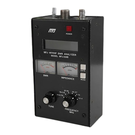
ANTENNA connector will damage this unit. Description The MFJ-259B RF analyzer is a compact battery powered RF impedance analyzer. This unit combines four basic circuits; a 1.8-170 MHz variable frequency oscillator, a frequency counter, a 50 ohm RF bridge, and an eight-bit micro-controller. -
Page 3: Typical Uses
Component limitations are another source of inaccuracy. Diodes detecting very small voltages are non- linear. The accuracy of the MFJ-259B is enhanced by the use of special microwave zero-bias Schottky detectors with matching compensating diodes. Each unit is individually compensated to provide the best possible linearity with both high and low impedance loads, making the A/D converter's 1/2 percent resolution the primary limitation. -
Page 4: Frequency Range
OFF-ON switch and power connector. This jumper is accessed by removing eight screws along the both sides of the MFJ-259B. After the cover mounting screws are removed, remove the entire back cover. The black plastic jumper fits over two of three adjacent pins. It must be properly positioned for the type of battery... -
Page 5: Using Rechargeable "Aa" Type Batteries
Typical battery charging current is 10-20 mA through an internal charging system. The internal charger trickle charges internal batteries any time a proper external voltage is applied, even when the MFJ-259B is turned off. The MFJ-1315 supply fulfills all power supply requirements. -
Page 6: Power Saving" Mode (Sleep Mode)
VOLTAGES CAN ALSO DAMAGE THIS UNIT. General Connection Guidelines The “ANTENNA” connector (SO-239 type) on the top of the MFJ-259B provides the RF measurement output connection. This port is used for SWR or other RF measurements, with the exception of the Frequency Counter mode. -
Page 7: Power-Up Display
The “FREQUENCY COUNTER INPUT” connector (BNC type) is for use as a frequency counter only. Note: The following is a description of the opening or default menu used by the MFJ-259B. This unit also has an advanced user section in section 4.0. -
Page 8: Blinking "Voltage Low" Display Warning
MFJ-259B Instruction Manual HF/VHF SWR Analyzer Coax Loss, the second mode, is reached by pressing the “MODE” button once. The liquid crystal display (LCD) indicates the test frequency and approximate loss of any 50 ohm coaxial cable, 50 ohm attenuator pad, or 50 ohm transformer or balun (for differential mode current only). -
Page 9: General Connection Guidelines
If the antenna does not use a dc grounded feed system, momentarily short the antenna lead from shield to center. This prevents static charges from damaging the MFJ-259B’s zero bias detector diodes. b.) Immediately connect (in the case of a non-dc grounded feed system) the antenna lead to the MFJ-259B “ANTENNA” connector. - Page 10 “transformer” actions of the feedline and other components between the antenna and the MFJ-259B. If the line is 50 ohms, this unit will always display the antenna’s true SWR, with the exception of a slight reduction in SWR with longer or more lossy feedlines.
-
Page 11: Coax Loss
Coax Loss The second main (or opening) mode is “Coax Loss”. Access this mode by turning the MFJ-259B on and stepping to the Coax Loss display. In this mode, the MFJ-259B LCD indicates frequency and coax loss in dB. The impedance meter is disabled in this mode. -
Page 12: Inductance
To measure capacitance: 1.) Turn the MFJ-259B on and step through with the mode switch until the “Capacitance in pf” display appears. 2.) Connect the capacitor across ANTENNA connector with the shortest leads possible, or with the lead length normally used in the working circuit. - Page 13 To measure inductance: 1.) Turn the MFJ-259B on and step the mode switch through until the “Inductance in uH” display appears. 2.) Connect the inductor across ANTENNA connector with the shortest leads possible, or with the lead length normally used in the working circuit.
-
Page 14: Advanced Operation
Transmit efficiency............SWR, impedance and forward power as a percentage of apparent power Forward In the ADVANCED mode, the MFJ-259B measures distance to fault, impedance, reactance, resistance, and standing wave ratio (SWR). It also measures and displays other terms used to describe SWR. These esoteric SWR descriptions include return loss, reflection coefficient, and transmitted power as a percentage of apparent power in the system. -
Page 15: General Connection Guidelines
Impedance is the first mode in the advanced menu. The opening display indicates: In this mode, the MFJ-259B LCD displays frequency, impedance or Z magnitude (in ohms), and phase angle ( θ ) of impedance. The meters indicate SWR and Impedance. The maximum impedance limit is set at 650 ohms,... -
Page 16: Return Loss And Reflection Coefficient Mode
Coaxial lines can lay in a pile or coil on the floor. Internal or external power can be used, and the MFJ-259B can be placed on or near large metallic objects with no ill effects. Coaxial lines connect normally, with the shield grounded. -
Page 17: Resonance Mode
Multiply the distance in feet by the velocity factor of the cable. The result is the physical distance in feet. Example: The MFJ-259B indicates 13 feet, and the cable is a standard foam cable with a velocity factor of 0.80. 13 multiplied by .80 is 10.5 feet. The fault is about 10.5 feet away. -
Page 18: Percentage Transmitted Power
The Resonance Mode primarily draws attention to reactance, displaying reactance on the IMPEDANCE meter. In this mode, the MFJ-259B measures frequency, SWR, resistance (R= ), and reactance (X= ). When reactance is zero, the system is said to be resonant. -
Page 19: Adjusting Simple Antennas
Select any mode that indicates SWR. Tuning basic antennas fed with 50 ohm coaxial cable can be accomplished with the following steps: 1.) Momentarily short the feedline center conductor and shield, then connect the feedline to the MFJ-259B. 2.) Adjust the MFJ-259B frequency to the desired frequency. -
Page 20: Testing And Tuning Stubs And Transmission Lines
Coaxial lines can lay in a pile or coil on the floor. Internal or external power can be used, and the MFJ-259B can be placed on or near large metallic objects with no ill effects. Coaxial lines connect normally, with the shield grounded. -
Page 21: Velocity Factor Of Transmission Lines
Coaxial lines can lay in a pile or coil on the floor. Internal or external power can be used, and the MFJ-259B can be placed on or near large metallic objects with no ill effects. Coaxial lines connect normally, with the shield grounded. -
Page 22: Impedance Of Transmission Lines Or Beverage Antennas
Coaxial lines can lay in a pile or coil on the floor. Internal or external power can be used, and the MFJ-259B can be placed on or near large metallic objects with no ill effects. Coaxial lines connect normally, with the shield grounded. -
Page 23: Adjusting Tuners
240,000 is 490. The impedance is 490 ohms. Using a potentiometer or resistor decade box: 1.) Connect the MFJ-259B to one end of the system (in this case you can use a broadband matching transformer). 2.) Adjust the frequency and note only the SWR change. -
Page 24: Testing Rf Transformers
The 25 to 100 ohm winding is connected through a very short (less than one electrical degree long) 50 ohm cable to the "ANTENNA" connector on the MFJ-259B. The other winding(s) of the transformer is terminated with a low inductance resistor equal to the desired load impedance. The MFJ-259B can then be swept through the desired transformer frequency range. -
Page 25: Testing Rf Chokes
Troublesome series resonances can be detected by installing the choke in the operating location, and connecting only the MFJ-259B from end to end through a short 50 ohms jumper cable. By slowly sweeping the operating frequency range of choke, dips in impedance identify low impedance series-resonant frequencies. By moving a small insulated screwdriver’s blade along the choke, you will find a point where the series resonate impedance...
Need help?
Do you have a question about the MFJ-259B and is the answer not in the manual?
Questions and answers