Advertisement
Quick Links
REMOTE SWITCHER UNIT CR6 INSTRUCTIONS FOR USE
42-663
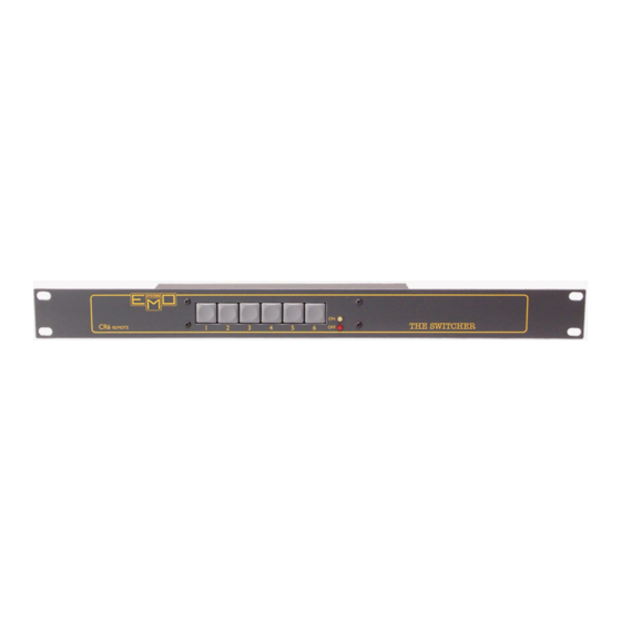
EMO Remote Switcher Unit CR6
WARNING: TO AVOID ELECTRICAL SHOCK READ THESE INSTRUCTIONS CAREFULLY
CONTENTS
1 Introduction
1.1 Safety
1.2 Description
2 Installation
2.1 Fixing
2.2 Keypad de-select
3 Wiring
4 Operation
5 Troubleshooting
These instructions apply to UK versions only.
1. INTRODUCTION
1.1. SAFETY
Mains power wiring is dangerous. A suitably qualified person
should install the system. Reference should be made to BS
& any other local wiring requirements Before working on
this system or altering any of the options, isolate the Master
Switcher CM6 and Slave Switcher CS6 units from the
electricity supply. When the supply is hard wired turn off the
local isolator and preferably remove the fuses. Ensure that all
staff know that you will be working on the system. If power
is supplied from a pluggable source, remove the plug.
This unit should be fitted in a suitable enclosure (19" rack)
to restrict access to the wiring terminals.
EMO Systems, Canford Audio Plc Crowther Road Washington,Tyne & Wear, NE38 0BW. UK
by Canford
TECHNICAL DATA SHEET
1.2 DESCRIPTION
The system allows mains powered electrical equipment to
be turned on and off in a particular sequence. Instructions
to initiate the sequence are input via a coded keypad. The
CR6 Remote Panel allows control from a location remote
to the CM6 Master Unit. The CM6 Master Unit contains all
the control electronics together with the first two sequential
power outputs. A further 8 low voltage outputs are available
to control CS6 Slave Units.
2. INSTALLATION
2.1 FIXING
All units are designed for mounting in a standard 19" rack.
2.2 KEYPAD DE-SELECT
When a CR6 Remote Panel is fitted to a system it is
sometimes necessary to prevent the keypad on the master
unit being able to operate the system. This can be achieved
by cutting a wire link on the keypad PCB in the master unit.
This link is situated on the LED end of the front panel PCB
and is accessible without removing the board from the unit.
This link only prevents the keypad from operating, it does
not disable the LED's so that the system status can be
checked.
3 WIRING
To give complete control and maximum security a 9 wire cable
is required to connect the remote panel to the master unit.
Wiring between the barrier strips is 1 to 1, 2 to 2 etc.
Connecting cables can be any suitable low voltage type,
e.g. burglar alarm or telephone. The use of spade crimps is
recommended. Low voltage cables should be segregated
from power (mains) cables.
It is possible to use the system with a reduced number of
wires in the control cable but this does allow the 'cracking' of
emosystems.co.uk
02-475 v2
Advertisement

Summary of Contents for Canford EMO CR6
- Page 1 (mains) cables. It is possible to use the system with a reduced number of wires in the control cable but this does allow the ‘cracking’ of EMO Systems, Canford Audio Plc Crowther Road Washington,Tyne & Wear, NE38 0BW. UK 02-475 v2...
- Page 2 CR6 remote keypad unit. Please read the full “Instructions for Use” of the Master Switcher unit CM6 for full details of the complete switching system. EMO Systems, Canford Audio Plc Crowther Road Washington,Tyne & Wear, NE38 0BW. UK 02-475 v2...
Need help?
Do you have a question about the EMO CR6 and is the answer not in the manual?
Questions and answers