Table of Contents

Related Manuals for Rego Macro CryoMac 3

Summary of Contents for Rego Macro CryoMac 3
- Page 1 Macro Technologies A RegO Brand ® CryoMac 3 Operation and Maintenance Manual ® SAFETY INSTRUCTIONS For your safety and improved service life of the product, please read this Manual before use and follow the safety instructions carefully.
- Page 2 Warning Installation, usage and maintenance of this product must be in compliance with all Macro Technologies, LLC Instructions as well as all requirements and provisions of national and local standards, codes, regulations and laws. Inspection and maintenance of a periodic basis is essential. Only qualified personnel should perform installation and maintenance.
-
Page 3: Table Of Contents
Table of Contents Key Features ....................2 Specifications ....................2 Product Description ..................3 Features and Benefits of the Stop Assembly New Features Designed to Address Icing Issues Operating Instructions ................... 4-5 Product Maintenance and Part Replacement ..........5-9 Maintenance Schedule ............... 5 Inspection Schedule Checklist ............ -
Page 4: Key Features
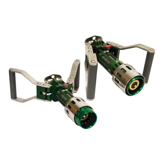
Key Features Specifications Fluid Compatibility: LNG, Methane and LN2 Thank you for purchasing the Macro Technologies CryoMac 3 LNG ® (Liquid Natural Gas) Fueling Nozzle (Part No. CryoMac3-50M and Maximum Refueling Pressure: 500 PSIG / 34.5 BAR CryoMac3-50M-S). We know that you will find it safe, easy to use and easy to service. -
Page 5: Product Description
Features and benefits of the Stop Assembly: Product Description The CryoMac 3 Stop Assembly has been re-designed to clear ice ® The CryoMac3-50M and CryoMac3-50M-S have three handle positions, Connected, Vent, and Open. In the Connected position from the Stop Assembly area. (Position 1 in Figure 1 below), the handles are pushed away from DIAGRAM OF NEW STOP ASSEMBLY the operator and the nozzle is locked onto the male receptacle and... -
Page 6: Operating Instructions
Operating Instructions NOTICE Frost build up in the slot area (red circled areas below) may prevent nozzle attachment and removal. If nozzle does not go onto receptacle, release the handles, depress Before fueling, be sure to connect the the Stop Assembly Lever, and then pull back the handles. ground cable. -
Page 7: Product Maintenance And Part Replacement
Uncoupling Nozzle after Fueling: Product Maintenance and Part Replacement Once the gases vent out of the nozzle from the exposed vent Maintenance Schedule holes until the venting stops (usually just a few seconds). All Macro technologies products are thoroughly tested to prevent If gases continue to vent for a prolonged period of time, check injury and malfunctions during use. -
Page 8: Inspection Schedule Checklist
CryoMac®3 Inspection Schedule Checklist Inspection Each Fueling Daily ü Before, during and after fueling check for any leaks ü Visually inspect items listed below: Cleanliness of Stop Assembly area ü (See Features and Benefits of the Stop Assembly) Check Sleeve for wear Replace ü... -
Page 9: Replacement Of Poppet Assembly And Seat/Seal Assembly
Replacement of Poppet Assembly and Seat/ Remove the old Poppet Assembly and Seat/Seal retainer. If the Nozzle is only leaking while connected, the current poppet Seal Assembly Assembly does not need to be replaced. However, it should still be carefully inspected to ensure that all sealing surfaces If the Nozzle is leaking only while connected to the receptacle you are clean and undamaged. -
Page 10: Replacement Of Interface Seal
Attach the Socket Wrench and torque to 45 - 50 Ft-Lbs. When Slide the seal ring onto the guide and let it rest on the seal. tightening with torque wrench, the final turns will exhibit higher levels of torque than by hand. This indicates the thread locking While holding the ring/seal combination as level as possible, system is engaging. - Page 11 Remove the four pins from the stainless Sleeve using the 5/32” 11. Place the Balls in the holes one by one by lowering the rubber Allen Wrench and store them in a safe place, these pins will be band, sliding the ball in, and then raising the rubber band back re-used later.
-
Page 12: Warranty
NOTICE If Macro Technologies, LLC furnishes technical advice to buyer, whether or not at buyer’ s request, with respect to application, further manufacture or other use of the products and parts, Macro Macro Technologies, LLC warrants products and repair kits manufactured by it to be free from Technologies, LLC shall not be liable for technical advice and buyer assumes all risks of such defects in materials and workmanship under normal use and service for a period of 12 months advice and the results thereof. -
Page 13: Trouble Shooting Guide
Trouble Shooting Guide: Issue Possible Cause Remedy Using dry compressed air or nitrogen, blowout all water and frost buildup. One Ice buildup on Stop Assembly can also move the handles back and forth 1. Difficulty depressing Stop Assembly between the vent position and fill position. If Spring Rest is missing. - Page 14 CryoMac 3 LNG Fueling Nozzle -- One Page Guide ® Coupling the Nozzle for fueling Step 1) Blow moisture off Nozzle Step 2) Push Safety Stop lever down to ensure Step 3) Push handles toward the Receptacle and Receptacle using dry handles are completely back, then as far as they will go, the fueling compressed air or nitrogen.
Need help?
Do you have a question about the Macro CryoMac 3 and is the answer not in the manual?
Questions and answers