Table of Contents
Advertisement
Advertisement
Table of Contents

Related Manuals for Yaesu FC-757AT


Summary of Contents for Yaesu FC-757AT
- Page 2 Este manual original foi gentilmente cedido para ser digitalizado por PY2TKI Marcos Digitalizado em 24 de Novembro de 2020 por Alexandre "Tabajara" Souza, PU2SEX http://www.tabalabs.com.br http://tabajara-labs.blogspot.com MANUAL DE DISTRIBUIÇÃO GRATUITA - Respeite o meu esforço de preservar a documentacao...
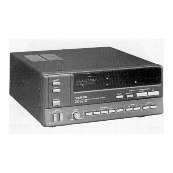
- Page 3 Two antenna jacks are provided, along with controls for remote automatic and manual selection of up to five antennas in total when the FC-757AT is used with the optional FAS- l -4R Remote Antenna Selector. An internal 50-ohm dummy load is included in the FC-757AT, along with an in-line RF wattmeter and a self-calculating (automatic) SWR meter.
-
Page 5: Front Panel Controls
SWR. However, if the SWR is high, the SWR null may be too sharp for the automatic If the FC-757AT is used with a transceiver designed sensing circuitry to notice, in which case the SENS to control the tuner automatically, such as the control must be set further counterclockwise. -
Page 6: Start Button
430 pF. The capacitance set manually will be stored in memory One of these ten green LEDs will be lit to indicate for that band. the selected MHz band to which the FC-757AT is set. START Button Antenna Selection Indicators This momentary contact button activates the auto... - Page 7 Tuner circuit from the RF line. This LED lights. can be used for receiving on frequencies that are outside of the matching range of the FC-757AT. If the red WARNING LED blinks during transmis In the undepressed position, the Tuner is in the sion, a severe mismatch is present at the selected RF line.
-
Page 8: Rear Panel Connections
REAR PANEL CONNECTIONS ® ANT A, B INPUT These type M coaxial jacks are for connection of This type M coaxial jack is for connection to the the antenna system(s). The ANT A jack is auto antenna jack transceiver, via supplied matically selected when the DC power to the connection cable A. -
Page 9: Antenna Considerations
INSTALLATION INTERCONNECTIONS ANTENNA CON SID ERA TIO NS Figures through the following pages The FC-757AT and FAS- l -4R Remote Antenna illustrate interconnections between various Selector are designed for unbalanced RF feedlines. models of HF equipment and the FC-757AT, and For antennas that require balanced feed, or for optional F A S- l -4R. - Page 11 FAS-l-4R FIGURE FC-757AT -m:JJ: :: :: :J 1 N Pur ANT B-2 I �' AND TRANSCEIVER l o j «lJ:::J -m:JJ: :: :: :J 41° 1 ;(Jl::: :J WHITE BLUE BLACK FT-77/S DODOO 0 ° OODDDDD 0000000 0000000 DODOO A N T �GND 13.5V...
-
Page 12: Operation
LED. or open circuit. Do not proceed until the cause is located and the fault corrected. Switch the FC-757AT POWER switch on, and then switch the transceiver on. Tune the transceiver (and Tuner, if... - Page 13 When using a transmitter on the amateur bands, set If the antenna is far from resonance (or if antenna the SEN S control fully counterclockwise to disable Q is high), and especially if you are using a trans the auto-tune system, and set the METER SWR/PO ceiver that has a broadband solid state power amplifier, the automatic final protection circuitry switch to the PO (undepressed) position.
- Page 14 However, if it is necessary to store the FC-757AT for a long period of time, the backup system may be switched off by moving the backup switch on the CPU Unit (beneath the top cover) to the right.
- Page 15 Connect the main coaxial feedline from the INPUT jack on the F A S- 1-4 R to the ANT B terminal on the FC-757AT, and connect the wire ends of the 4-conductor cable from the REMOTE jack on the FAS- l -4R to the REMOTE terminal strip on the...
-
Page 16: Top View
ALIGNMENT The FC-757AT has been carefully aligned at the The following tools and equipment are required for factory, and with normal use it should not require alignment: realignment, although the lithium battery may One 17-ohm non-reactive dummy load (or three require replacement after five years. - Page 17 CM Coup ler Balance Connect the inline wattmeter with 50-ohm dummy load to the ANT A jack, and set the FC-757AT and transceiver to the 1 4 MHz band. On the FC-757AT,press the ANTENNA A button, and set the THRU switch to the depressed position and the SWR/PO switch to the SWR (depressed) position.
- Page 18 Backup Battery Replacement Variable Capacitor Presetting To determine whether the lithium backup battery This procedure involves a combination of mechan needs to be replaced, measure the DC voltage ical and electrical adjustments that determines the between the top of the battery (exposed side) and position-sensing parameters used by the CPU to ground.
-
Page 22: Parts List
PARTS LIST M AIN CH ASSIS S4000027 FOOT (REAR) R3100700 FOOT (FRONT) Symbol N o. Part N o . Description POTENTIOMETERS R0100690 WIRE STAND J60800103 K1611007AC50KA 50kUA VRl,2 CAPACITORS O.Ol µ F K13179008 Ceramic disc SOWV F CPU UNIT (DD106F103Z50V) Symbol No. - Page 23 Carbon film 1/4W SJ 47kn 102245473 Rll 2-120,164, L I T H I UM BATTER Y 193,0201 BAT101 Q9000106 CR-2025 R197 1012454 73 TJ 47kn R122 102245563 56kn R151,199,0200 102245823 82kn R144-149 101245104 TJ lOOkn R158,159,161 J02245104 lOOkn R107 102245154 150kn TUN E R UN IT R152-154...
- Page 24 RE LAYS RELAY RL201 -203 M 1 1 90026 RL301 Ml190026 MR-31 SWI TCH S201 N00,50069A S R32HP3-3-10 DUM M Y L O A D UNIT P L UGS Symbo l N o . Part N o . Desc r i p t i o n P201 T9204746 XHP-11...
- Page 25 POT E N T I OMETER VR6 0 1 160800 1 0 2 K 1 2 1 LOZ04- 1 0KB l Ok.nB SWI TCHES N4 090049 KHC 1 0 9 0 1 S60 1 -6 1 2 S6 1 3 - 6 1 5 N4090085 SPH2 SWITCH B UNIT...
- Page 26 M EM O...
- Page 28 YA E S U E84201 84AC8 4 0 1 -A)
Need help?
Do you have a question about the FC-757AT and is the answer not in the manual?
Questions and answers