Table of Contents
Advertisement
Quick Links
ControlLogix 7252 LDT Interface Manual
Revision 1.5
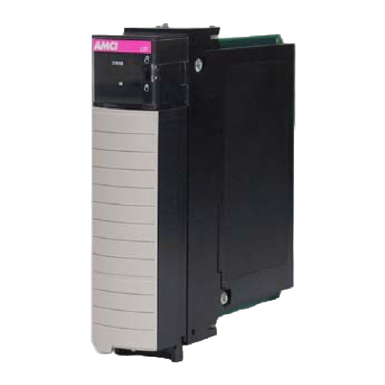
Module Overview
The 7252 module is a two-channel LDT interface module that resides in a Rockwell Automation
ControlLogix rack.
This module is capable of connecting up to two independent LDT sensors with max 32-bit resolution for
position. This module also has two latching inputs, one for each channel, which can be used to capture the
sensor's data.
The 7252 module communicates with the PLC using input and output registers. The Data value, Velocity,
Latched Value, and Status information are reported to the Input Registers. All module setup parameters,
including Preset Value, Count Direction and Velocity Response Time are programmed through Message
Instructions.
The Output registers assigned to the module can be used to Apply the Preset or to send the PLC's Central
System Clock-Time to the 7252 module. This optional and additional feature causes the module to use this
system time and the sensors velocity data to calculate an Interpolated or "Look Ahead" Data value.
The 7252 module stores its parameters in a non-volatile flash memory when power is removed so it is not
necessary to program the module at every power up. However, this flash memory is good for a minimum of
10,000 write cycles, so the module must not be programmed during every machine cycle.
The module has two opto-coupler latching inputs that will capture the scaled sensor data on the rising,
falling, or both transitions of the input. These inputs can be wired to be sinking or sourcing and will activate
when they see a voltage level between 8 and 24Vdc across the + and – latch terminals.
Through the use of different rack Assembly Instances, the 7252 can be configured to operate with one or two
of the available channels. Disabling the unused channel is recommended for improving the throughput time.
20 Gear Drive, Plymouth Industrial Park, Terryville, CT 06786
page: 1
Tel: (860) 585-1254
Fax: (860) 584-1973
Web: www.amci.com
Advertisement
Table of Contents

Related Manuals for AMCI ControlLogix 7252 LDT

Summary of Contents for AMCI ControlLogix 7252 LDT
- Page 1 ControlLogix 7252 LDT Interface Manual Revision 1.5 Module Overview The 7252 module is a two-channel LDT interface module that resides in a Rockwell Automation ControlLogix rack. This module is capable of connecting up to two independent LDT sensors with max 32-bit resolution for position.
-
Page 2: General Information
ADVANCED MICRO CONTROLS, INC. warrants that all equipment manufactured by it will be free from defects, under normal use, in materials and workmanship for a period of [18] months. Within this warranty period, AMCI shall, at its option, repair or replace, free of charge, any equipment covered by this warranty which is returned, shipping charges prepaid, within one year from date of invoice, and which upon examination proves to be defective in material or workmanship and not caused by accident, misuse, neglect, alteration, improper installation or improper testing. - Page 3 ControlLogix 7252 LDT Interface Manual Revision 1.5 Table of Contents Installing the 7252 Module Chapter 1 Hardware Overview Chapter 2 Module Specifications Front Panel & LED Function Connector Pinout Latching Input Wiring Wiring Notes LDT Modes and Signals Programmable Parameters...
-
Page 4: Chapter 1: Installing The 7252 Module
Chapter 1: INSTALLING THE 7252 MODULE Configuring the ControlLogix System 1. Open RSLogix 5000 and the project in which you want to install the AMCI 7252 module. 2. Right click on I/O Configuration in the Project Tree. 3. Select New Module. -
Page 5: Chapter 2: Hardware Overview
Operating Temperature: 0 to 60° C Relative Humidity: 5 to 95% (non-condensing) Storage Temperature: -40 to 85° C EDS File An EDS file for the 7252 module can be downloaded from the Tech Library section of AMCI’s website, www.amci.com. FLASH Memory The 7252 module’s parameter values are stored in a non-volatile Flash memory. - Page 6 ControlLogix 7252 LDT Interface Manual Revision 1.5 Front Panel: Status LED AMCI LDT Solid Red Data Flash Memory Fault Status Blinking Red/Green Module Hardware Comm. Failure Blinking Red Non Clearable Transducer Fault Blinking Green Clearable Transducer Fault Solid Green No Errors...
-
Page 7: Connector Pinout
ControlLogix 7252 LDT Interface Manual Revision 1.5 Connector Pin Out: The input connector consists of a Removable Terminal Block with the Rockwell Automation Part Numbers 1756- TBCH (36 position cage clamp) or 1756-TBS6H (36 position spring clamp). The terminal block is not supplied with the 7252 module. -
Page 8: Wiring Notes
Because the rack cabinet is typically better grounded than the machine, AMCI recommends that the cable shields be terminated at the 7252 module. However, if your cable shield is attached to the sensor’s housing, and the sensor is grounded through its mounting, you must not connect the cable shields to the 7252 module because this will create a ground loop. - Page 9 ControlLogix 7252 LDT Interface Manual Revision 1.5 LDT Modes and Signals The 7252 module supports four type of LDT transducer signaling: 1. Start/Stop Mode The Start/Stop signal interface of the 7252 module is differential RS-422 output. The module initiates a start pulse a minimum of 1.0 microsecond in duration.
- Page 10 ControlLogix 7252 LDT Interface Manual Revision 1.5 3. PWM Mode 1 (Variable Pulse with External Interrogation) – 7252 Default Mode In PWM Mode 3, the signal interface is a pulse-width modulated RS-422 signal. In this mode the 7252 module is configured for external interrogation and generates a start pulse to begin measurement.
-
Page 11: Chapter 3: Programmable Parameters
ControlLogix 7252 LDT Interface Manual Revision 1.5 Chapter 3: Programmable Parameters The 7252 is configured by programming its Programmable Parameters. These parameters are broken down into three groups, Module Setup, LDT Setup, and Data Setup parameters. The 7252 uses two methods for the programming and monitoring of data. Input and Output registers are used to program and monitor data that occurs on a regular schedule, such as reading the data value and status information or setting the system time. - Page 12 ControlLogix 7252 LDT Interface Manual Revision 1.5 LDT Mode – Three Configuration Word bits are used to select the desired LDT mode, which can be one of the four modes described in Chapter 2: • Start/Stop Mode (default) • Control Pulse Mode •...
- Page 13 Interpolated Data Value along with the time value can be sent to other ControlLogix modules, for example the AMCI 8213-VA, allowing them to schedule their responses with a high degree of precision. Two, the Interpolated Data Value allows the user to “Look Ahead” to what the Data Value will be at a defined time in the future. Here is the procedure for generating the Interpolation Data Value.
-
Page 14: Chapter 4: Message Instructions
ControlLogix 7252 LDT Interface Manual Revision 1.5 Chapter 4: Message Instructions The programming of the 7252 module’s Setup data requires the use of Message Instructions. The format of this instruction is shown below. 1. A different message instruction is needed for each channel of the 7252 module. - Page 15 ControlLogix 7252 LDT Interface Manual Revision 1.5 Source Length: If the Message Instruction is being used to send data to the 7252 module, then the Source Length parameter must be equal to 28 bytes. If the Message Instruction is being used to read data from the 7252 module, then the Source Length Parameter must be set to zero.
- Page 16 ControlLogix 7252 LDT Interface Manual Revision 1.5 Message Configuration – (Communication Tab) When the Configuration window shown above is completed, click on the Communication tab. The following window will open. Click on the Browse button and set the path parameter to the slot where the 7252 module is located. All of the remaining Communication parameters can remain at their default settings.
-
Page 17: Chapter 5: Setup Data
ControlLogix 7252 LDT Interface Manual Revision 1.5 Chapter 5: Setup Data The message instructions described in chapter 4 above are used to send the setup data to the two channels of the 7252 module. This data consists of seven 32 bit words (28 bytes) shown in the following table. Each channel can be programmed with different setup data. -
Page 18: Chapter 6: Reading Status Data
ControlLogix 7252 LDT Interface Manual Revision 1.5 Note 3: The 7252 module will accept and act on Setup Data sent from a Message Instruction that occurs in a Listen Only Processor. Note 4: The gradient value is entered with an assumed decimal point. For example, a gradient of 9.1234 would be entered as 91234. -
Page 19: Chapter 7: Input & Output Data
ControlLogix 7252 LDT Interface Manual Revision 1.5 Chapter 7: Input & Output Data Input Registers: (Data sent from the 7252 module to the PLC) The input data consists of five (for 1 channel) or ten (for 2 channels) 32-bit words, and is read by the PLC at the RPI (Requested Packet Interval) Time that is asynchronous to the Ladder Logic Program. -
Page 20: Description Of The Status Word
That is, you will have to use message instructions to program your setup data at every power up. If you do not want to use the module in this way, it must be returned to AMCI for repair. Bits 16 to 31: Reserved for future use... - Page 21 ControlLogix 7252 LDT Interface Manual Revision 1.5 Input Register Description Data Value: This register contains the position data from the sensor after it has been scaled, and after the Count Direction, Measurement Unit, and Preset Value have been applied. Range is from -2,147,483,648 to +2,147,483,647 Velocity: This is the rate of change of the data value in Counts / Second.
- Page 22 ControlLogix 7252 LDT Interface Manual Revision 1.5 Output Registers: (Data sent from the PLC to the 7252 module) The output registers are used to execute commands that typically occur during machine operation, while module setup functions are accomplished with the use of Message Instructions. See chapter 3 and 4 for configuring the 7252 module.
- Page 23 ControlLogix 7252 LDT Interface Manual Revision 1.5 Interpolation Command Programming Cycle 1. The ladder logic program reads the desired Central System Time value from the PLC using a GSV instruction. The Destination tag must consist of at least two DINT registers.
-
Page 24: Chapter 8: Manual Revision History
ControlLogix 7252 LDT Interface Manual Revision 1.5 Chapter 8: Manual Revision History Revision 0.0 was created 10/20/08 and was the initial release of the specifications Revision 1.0 was created on 1/30/09. The I/O and configuration words were updated. Revision 1.1 was created on 2/20/09. Position data values ranges were updated.
Need help?
Do you have a question about the ControlLogix 7252 LDT and is the answer not in the manual?
Questions and answers