Table of Contents
Advertisement
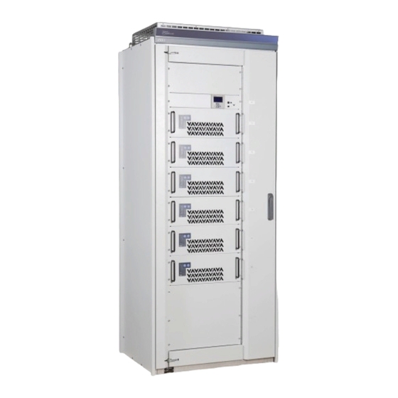
Charging Rectifier
This manual must be read before installation, use or work on the product.
This product contains dangerous voltages that when touched can cause electric shock, burns
or death.
The product must be installed by qualified personnel and according to the installation
instructions. Service may only be performed by authorized service personnel. The protective
covers and contact safety devices inside the equipment may only be removed by authorized
service personnel.
The power must always be disconnected in a safe way before starting any
service/maintenance.
Warning for reverse voltage. Power is supplied from several sources.
KraftPowercon Sweden AB, Hjalmar Petris väg 49, S-352 46 Växjö, Sweden, Tel: +46 470-705200, Fax: +46 470-705201,
Manual for
type PRX3
SAFETY INSTRUCTIONS
www.kraftpowercon.com
Manual: 9-1636-B
P/n: 0001085
Advertisement
Table of Contents

Related Manuals for Kraft Powercon PRX3

Summary of Contents for Kraft Powercon PRX3
- Page 1 Manual for Charging Rectifier type PRX3 SAFETY INSTRUCTIONS This manual must be read before installation, use or work on the product. This product contains dangerous voltages that when touched can cause electric shock, burns or death. The product must be installed by qualified personnel and according to the installation instructions.
- Page 2 We reserve the right to make changes to the content of this manual without prior notification. KraftPowercon Sweden AB, Hjalmar Petris väg 49, S-352 46 Växjö, Sweden, Tel: +46 470-705200, Fax: +46 470-705201, www.kraftpowercon.com...
- Page 3 KraftPowercon Sweden AB, Hjalmar Petris väg 49, S-352 46 Växjö, Sweden, Tel: +46 470-705200, Fax: +46 470-705201, www.kraftpowercon.com...
-
Page 4: Table Of Contents
CONTENTS 1 PRESENTATION ....................6 2 SAFETY INSTRUCTIONS ..................7 3 TECHNICAL DATA ....................8 ASSORTMENT ............................... 8 Electrical data ..............................8 3.2.1 Electrical input data ..........................8 3.2.2 Electrical output data ..........................8 ENVIRONMENTAL DATA ........................9 MECHANICAL DATA ..........................9 CONFORMITY WITH STANDARDS ....................... 9 4 FUNCTIONAL DESCRIPTION...............10 GENERAL..............................10 RECTIFIER MODULES..........................10... - Page 5 6 INSTALLATION INSTRUCTIONS ..............17 SAFETY INSTRUCTIONS ..........................17 GENERAL..............................17 STORAGE AND PROTECTION .......................17 MOUNTING ..............................17 6.4.1 General ..............................17 6.4.2 Erection of cubicle ...........................17 6.4.2.1 Cubicle type F27 ..........................17 6.4.2.2 Cubicle type F41 ..........................18 6.4.2.3 Cubicle type S39 ..........................18 6.4.3 Mounting of rectifier modules ......................18 6.4.3.1 General ..............................18 6.4.3.2...
- Page 6 Appendices LAYOUT AND DIMENSION DIAGRAM PRX3, CUBICLE TYPE F27 LAYOUT AND DIMENSION DIAGRAM PRX3, CUBICLE TYPE F41 LAYOUT AND DIMENSION DIAGRAM PRX3, CUBICLE TYPE S39 DIMENSION DIAGRAM RECTIFIER MODULE PRM3 CIRCUIT DIAGRAM PRX3 CIRCUIT DIAGRAM RECTIFIER MODULE PRM3 KraftPowercon Sweden AB, Hjalmar Petris väg 49, S-352 46 Växjö, Sweden, Tel: +46 470-705200, Fax: +46 470-705201,...
-
Page 7: Presentation
PRESENTATION PRX3 is a complete modular charging rectifier for total output power up to 54 kW. The main parts of the system are 3-phase rectifier modules type PRM3 working in parallel aimed for mounting in 19” cabinet, monitoring unit type PCM2 specially designed for DC systems and also fuses and disconnectors for highest safety and easy service and maintenance. -
Page 8: Safety Instructions
SAFETY INSTRUCTIONS This product contains dangerous voltages that when touched can cause electric shock, burns or death. For safety reasons the concerned personnel are classified according to the following requirements for specific skills. Authorised service personnel: • Have electrical training and adequate experience to avoid the dangers that electricity can cause. -
Page 9: Technical Data
Rect. module Cubicle/weight Power Model Output Mains Mains Mains Terminal Terminal loss** Number I F27 F41 S39 RAT ED RAT ED PRX3 power power* current* fuse gL/gG 110/70 10.6 90 90 190 110/140 21.2 110 110 210 110/210 31.8 130 230... -
Page 10: Environmental Data
Ripple current..........<1 % of rated current Efficiency, typical .......... >92 % at 3x400 V Other, see table in section 3.1 ASSORTMENT. ENVIRONMENTAL DATA Class of enclosure ............IP21 as per EN 60529 Cooling................Temperature controlled fans in rectifier modules, otherwise natural convection Ambient temperature .......... -
Page 11: Functional Description
FUNCTIONAL DESCRIPTION GENERAL PRX3 is a complete charging rectifier equipped with up to six rectifier modules of the type PRM3 working in parallel with three-phase mains power feeding. The monitoring unit PCM2 is built in for monitoring of both rectifiers, battery and other parts of the complete DC system. For each rectifier module there are fuse links for both AC and DC that can be used as disconnection for safe and easy maintenance and service. -
Page 12: Current Control
4.2.8 Loadsharing In the PRX3 up to 6 rectifiers can be working in parallel while sharing the load using so called active loadsharing. The loadsharing is active in the range of about 10 – 90 % of the rated current. -
Page 13: Over-/Undervoltage Ac
4.3.1 General A complete rectifier system of the type PRX3 may, depending on model, hold up to 6 rectifier modules in parallel of the type PRM3. Here, only the most considerable functions are described. For more information, see Manual for monitoring unit PCM2. -
Page 14: Float Charging
4.3.2 Float charging Float charging is the normal operating mode determined by the battery. The voltage level is to be set according to the battery manufacturer instructions. For more information, see the Manual for monitoring unit PCM2. 4.3.3 Equalizing charging Equalizing charging means charging with raised voltage level during a limited period. -
Page 15: Operation
OPERATION GENERAL The bulk of the operation is associated to the monitoring unit. This is described in the Manual for monitoring unit PCM2. Other operation is detailed in this section. RECTIFIER MODULES 5.2.1 General The front panel of the rectifier module has push-buttons for manoeuvring of the module together with a number of led indication lamps. -
Page 16: Ac Ok
5.2.3.1 AC OK AC OK will be put on with green light if the mains supply is OK. All indications put out, AC OK included, indicates that there is no mains supply. AC OK put out while the ALARM-led is red indicates that there is mains supply but not within limits. -
Page 17: Indication Table
5.2.3.5 <Indication table Indication Interpretation STBY ALARM Green Put out Green Green Put out Normal operation 1. U low, 50-82% of U Green Put out Green Green 2. I limited due to high temperature 3. Fan fault Green Put out Green low, <50% of U Green... -
Page 18: Installation Instructions
INSTALLATION INSTRUCTIONS SAFETY INSTRUCTIONS WARNING! This product contains dangerous voltage that when touched can cause electric shock, burns or death. Protective earth must always be connected in a reliable way to avoid the risk of live parts in the equipment in the event of faults. No live parts are permitted during installation. The product must be installed by qualified personnel (see section 2 SAFETY INSTRUCTIONS). -
Page 19: Cubicle Type F41
mm free space must be left to the wall to ensure sufficient ventilation. Cable inlet is either from beneath through an opening in the bottom plate (see layout drawing F27 in Appendix A) or via an FL21 flange through the roof-plate. 6.4.2.2 Cubicle type F41 P C M 2... -
Page 20: Cubicle Type S39
Fasten the modules with four screws onto the rack frame using the holes on the short sides of the module. ELECTRICAL INSTALLATION 6.5.1 General PRX3 is designed for permanent installation only. Protective earth must be connected before any other installation. 6.5.2 Grounding For ground wire connections up to 10 mm the multi- pole brass connector is used. -
Page 21: Mains Voltage
S39. The phase sequence is of no consequence. The ground wire is connected according to the previous section. Note that PRX3 is intended exclusively for TN earthing system network. Unique for cubicle S39 with 440V rated DC voltage and four or more rectifier modules, is that 230V AC auxiliary power has to be supplied to terminal X10:4 and 5. -
Page 22: Rectifier Modules
6.5.6 Rectifier modules 6.5.6.1 Cubicle type F27 and F41 By this time, the rectifier modules should have all cable sets connected on the rear of the module (see section 6.4.3.2) and the other end of the cable sets should hang down on the inside of the cubicle visible from the front. -
Page 23: Commissioning
COMMISSIONING SAFETY INSTRUCTIONS DANGER! This product contains dangerous voltages that when touched can cause electric shock, burns or death. All contact safety devices and plates must be fitted when operating. Ensure that the apparatus has been in a dead condition for at least 5 minutes before any protective coverings are removed, giving the internal circuits time to discharge. -
Page 24: Checking The Charging Voltage
After a 5-10 seconds delay, the rectifier modules will start, but most likely in standby mode (depending on the condition when they where last turned off). Start the modules one by one in raising order by pushing the ON-button. The battery now starts to charge, and if it was in a state of deep discharge, the charging starts with rated current until the float charging level is reached. -
Page 25: Maintenance
MAINTENANCE ANNUAL INSPECTION 8.1.1 General In addition to these instructions, you must observe the instructions for maintenance in the Manual for monitoring unit PCM2 and the battery manufacturer's maintenance instructions. 8.1.2 Checking the charging voltage Connect a voltmeter to the test contacts (see section 5.3 MONITORING UNIT PCM2). -
Page 26: Fault Tracing And Service
FAULT TRACING AND SERVICE SAFETY INSTRUCTIONS DANGER! This product contains dangerous voltages that when touched can cause electric shock, burns or death. Ensure that the apparatus has been in a dead condition for at least 5 minutes before any action, giving the internal circuits time to discharge. - Page 27 The rectifier module's green indicator lamp ”AC OK” is lit and ”DC OK” is off Cause 1: The rectifier module is in standby mode which is a normal condition. Cause 2: The input ”EXT. FAULT” is used as external blocking and is in open state. Only valid if all modules shares the same symptom.
-
Page 28: Instructions For Replacing Rectifier Module During Operation (Hot Swap)
Cause 2: Some fault conditions, like for instance communication fault or first module out of operation, will stop active loadsharing. INSTRUCTIONS FOR REPLACING RECTIFIER MODULE DURING OPERATION (HOT SWAP) It is possible to replace a single rectifier module while the other still are in operation. The method is slightly different depending on type of cubicle. -
Page 29: Enclosure Type S39
Switch on the AC input power MCB, then the DC output MCB. The module is now ready to be started by using the buttons on the front panel. 9.4.2 Enclosure type S39 Begin with turning off the AC input power for the module by switching off the corresponding MCB (F11 for module T1, F12 for module T2, etc.) Also turn off the DC output power for the module by switching off the corresponding MCB (F31 for module T1, F32 for module T2, etc.) - Page 30 Appendix A LAYOUT AND DIMENSION DIAGRAM PRX3, CUBICLE TYPE F27 KraftPowercon Sweden AB, Hjalmar Petris väg 49, S-352 46 Växjö, Sweden, Tel: +46 470-705200, Fax: +46 470-705201, www.kraftpowercon.com...
- Page 31 Appendix B LAYOUT AND DIMENSION DIAGRAM PRX3, CUBICLE TYPE F41 KraftPowercon Sweden AB, Hjalmar Petris väg 49, S-352 46 Växjö, Sweden, Tel: +46 470-705200, Fax: +46 470-705201, www.kraftpowercon.com...
- Page 32 Appendix C LAYOUT AND DIMENSION DIAGRAM PRX3, CUBICLE TYPE S39 KraftPowercon Sweden AB, Hjalmar Petris väg 49, S-352 46 Växjö, Sweden, Tel: +46 470-705200, Fax: +46 470-705201, www.kraftpowercon.com...
- Page 33 Appendix D DIMENSION DIAGRAM RECTIFIER MODULE PRM3 * In addition ~30mm for plug connector and wires KraftPowercon Sweden AB, Hjalmar Petris väg 49, S-352 46 Växjö, Sweden, Tel: +46 470-705200, Fax: +46 470-705201, www.kraftpowercon.com...
- Page 34 Appendix E CIRCUIT DIAGRAM PRX3 KraftPowercon Sweden AB, Hjalmar Petris väg 49, S-352 46 Växjö, Sweden, Tel: +46 470-705200, Fax: +46 470-705201, www.kraftpowercon.com...
- Page 35 KraftPowercon Sweden AB, Hjalmar Petris väg 49, S-352 46 Växjö, Sweden, Tel: +46 470-705200, Fax: +46 470-705201, www.kraftpowercon.com...
- Page 36 Appendix F CIRCUIT DIAGRAM RECTIFIER MODULE PRM3 KraftPowercon Sweden AB, Hjalmar Petris väg 49, S-352 46 Växjö, Sweden, Tel: +46 470-705200, Fax: +46 470-705201, www.kraftpowercon.com...
- Page 37 KraftPowercon Sweden AB, Hjalmar Petris väg 49, S-352 46 Växjö, Sweden, Tel: +46 470-705200, Fax: +46 470-705201, www.kraftpowercon.com...
- Page 38 KraftPowercon Sweden AB, Hjalmar Petris väg 49, S-352 46 Växjö, Sweden, Tel: +46 470-705200, Fax: +46 470-705201, www.kraftpowercon.com...
- Page 39 KraftPowercon Sweden AB, Hjalmar Petris väg 49, S-352 46 Växjö, Sweden, Tel: +46 470-705200, Fax: +46 470-705201, www.kraftpowercon.com...
Need help?
Do you have a question about the PRX3 and is the answer not in the manual?
Questions and answers