Table of Contents
Advertisement
Quick Links
Product Summary
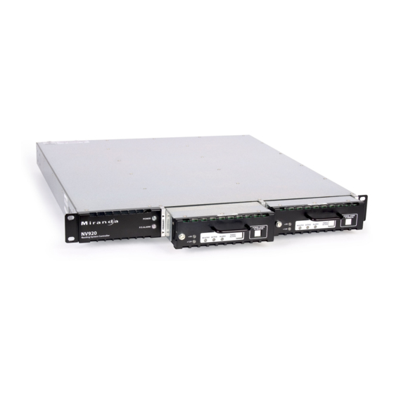
Your Miranda shipment contains an NV920 frame contain-
ing one or two NV920 system controllers and power supplies,
power cords, and this Quick Start guide. Depending on your
order options, the shipment might also include cables and
peripheral devices. See Figure 1.
An NV920 system controller allows you to configure and
operate routers, control panels, and other connected equip-
ment. A complete NV920 control system includes several
parts that work together:
NV920 system controller(s).
•
NV9000-SE Utilities configuration software.
•
PCs running configuration or control software.
•
Routers.
•
Control panels (physical or virtual).
•
Optionally, master control components.
•
Optionally, automation, UMD, monitor walls, and other
•
subsystems.
Control Systems
The NV920 is a member of Miranda's NV9000 family of sys-
tem controllers. In order of price and performance, the series
includes these control systems:
NV960
•
Each NV960 system controller is 2RU, has 2 disk drives,
and 3 PCI expansion slots. Two of the expansion slots typi-
cally provide Ethernet connections. The remaining expan-
sion slot can be used for other purposes such as
connecting serial devices.
Several models of the NV960 are available.
NV920
•
Each NV920 is 1RU and houses two system controllers.
Each system controller has 2 disk drives, 3 Ethernet ports,
and no expansion slots. However each NV920 does have
an RS-485 port that supports one serial device.
Several models of the NV920 are available. as listed on this
page.
NV915
•
Each NV915 system controller is 1RU, has one disk drive, 2
Ethernet ports, and no expansion ports. One of the Ether-
net port is available to support routers and control panels.
(Older NV915s had compact flash and no disk drive.)
The NV960, NV920, and the NV915 run the same software.
The NV920 is priced between the NV960 and the NV915.
A system controller is a device that (1) receives commands
from control panel operators or from third-party systems, (2)
Product Number: QG0014-01 Revision: A0; Date: 4/29/13
QuickStart Guide
NV920 Control System
and Accessories
Figure 1. Package Contents
NV920
Power cords
Software and
Documentation CD
dispatches instructions to routers, and (3) returns status
information to the control panels or to automation.
The NV920 product line includes these items:
NV920D. NV920 frame with dual controllers.
•
NV920S. NV920 frame with a single controller.
•
NV920-PRI. A primary NV920 system controller.
•
NV920-SEC. A secondary NV920 system controller.
•
NV920-FME. An NV920 frame only.
•
NV920-FRU. A "field replacement unit," that is, a spare
•
system controller.
The NV920
The NV920 frame is a 1RU frame which contains a power sup-
ply having two removable power supply modules, and one or
two removable NV920 system controllers. See Figure 2.
One controller is labeled 'Primary' and the other 'Secondary'.
These terms distinguish one from the other, but otherwise
have no specific meaning.
The NV920 frame has two power supply modules for redun-
dancy. In normal operation, both supplies operate in tan-
dem, sharing the load. If one power supply module fails, the
other immediately absorbs the full load.
If the NV920 frame has two system controllers, it is for redun-
dancy. One of the system controllers is active; the other is
stand-by. If the active system controller fails, the stand-by
system controller takes over.
QuickStart Guide
(this document)
1
Advertisement
Table of Contents

Related Manuals for Belden Miranda NV920

Summary of Contents for Belden Miranda NV920
- Page 1 QuickStart Guide NV920 Control System and Accessories Product Summary Figure 1. Package Contents Your Miranda shipment contains an NV920 frame contain- ing one or two NV920 system controllers and power supplies, NV920 power cords, and this Quick Start guide. Depending on your order options, the shipment might also include cables and peripheral devices.
-
Page 2: The System Controller
Figure 2. NV920 Power LEDs Primary System Controller Secondary System Controller Front View Rear View Power Failure Alarm Mute Button Connectors for Secondary System Controller Connectors for Primary System Controller PS 2 PS 1 The power supplies are removable (replaceable) from the rear perform diagnostic and maintenance tasks using XP’s normal of the frame. -
Page 3: Master Control
Alarm. This LED is normally off, but turns red when an • Master Control alarm condition is present in the controller. It is possible Master Control is a name given to an optional subsystem that for each controller in a dual-controller frame to show an allows operators to transition program output from one alarm. - Page 4 Follow these steps to mount the NV920: Figure 4. Frame Support 1) Locate the mounting hardware attached to the side of the NV920 frame. There are two metal parts for each side of the frame. Unscrew the metal parts from the frame. (front of unit) 2) Referring to Figure 4, attach the two small parts (with the slot) to the posts at the rear of the frame at the height at...
- Page 5 Referring to Figure 5, follow these steps to make system con- A Panel/Router Network and a Master Control Network troller connections: Figure 6, below, diagrams a redundant system that uses 1) Connect routers to the system controller. NVNET 1 for a network of panels and routers •...
- Page 6 (Each MCE in the NV5100MC frame connects to the mas- The system controllers in a redundant system must be configured identically (except for their IP addresses, of course). ter control Ethernet switch. The NV5100MC itself con- nects to the NV920 through the NV920’s router network.) Installation Steps To install NV9000-SE Utilities on a PC, follow these steps: Configuration PCs...
- Page 7 3) When you launch the installer, the ‘Welcome’ screen 6) Click ‘Install’. The installation then begins. It takes less appears after several seconds: than a minute. NV9000-SE Utilities provides online help, which provides some orientation for new users and detailed information for experienced users.
-
Page 8: Sample Configuration
(The IP addresses you enter should belong to the configu- The system controller icon must be green, otherwise the page does not open. Yellow icons represent system with warning- ration and monitoring network to which your PC level errors. Red icons indicate severe errors or disconnected belongs.) systems. -
Page 9: Other Topics
Click ‘Router Control System’. The next window appears: Choose an output and an input and click the ‘Take’ but- ton. To lock an output, choose an output and click ‘Lock’. Click ‘Sample Database’. The folder containing the data- base opens. It contains a .zip file that you should copy to The take and the lock appear in the list. - Page 10 3) Select Internet Protocol (TCP/IP). Click ‘Properties’ again: 2) Login to the system controller (which you will see is run- ning Windows XP embedded). 3) Go into Windows ‘Network Connection’ on the controller and find one of the Ethernet ports. 4) Give it an IP address (and subnet mask) that is unique on your facility’s network.
-
Page 11: Serial Port
Serial Port System Controller Specifications The serial port provides RS-485 communication on a male Spec Data DE9 connector. This is the pinout of the serial port: Weight 29.8 lb (13.5 kg) Processor Intel, Atom, N450, 1.6 GHz Windows XP Embedded 2 GB Tx–...
Need help?
Do you have a question about the Miranda NV920 and is the answer not in the manual?
Questions and answers