Table of Contents
Advertisement
Quick Links
Advertisement
Table of Contents

Summary of Contents for Arcus ARCUSPHASE DSP 1x VDS
- Page 1 INSTRUCTION FOR USE GA240GB-09.19 ARCUSPHASE DSP 1x VDS...
- Page 2 All rights reserved on this instruction for use, also for reproduction in any form, if photo mechanic, printed, on any kind of data carrier or in translated form. Reproduction of this instruction for use, even in excerpts, only with written permission of ARCUS Schiffmann.
-
Page 3: Table Of Contents
GA240GB-09.19 CONTENTS FIELD OF APPLICATION AND USAGE ............5 SAFETY INFORMATION ..................6 Instruction for use: special remarks ............6 ARCUSPHASE DSP: special remarks ............6 Required qualification of operating personnel ..........7 Prevention of dangers ................7 DESCRIPTION OF VOLTAGE DETECTOR .............9 UNPACKING AND EXAMINATION ..............10 START OF OPERATION .................11 STORAGE AND TRANSPORT ...............11 MEASURING LINE ..................11... - Page 4 GA240GB-09.19 CONTENTS PERIODIC TESTING OF COUPLING PARTS AND VOLTAGE TEST ...27 FREQUENCY MEASUREMENT ..............31 OSCILLOSCOPE ....................33 FFT ........................35 CONFIGURATION OF OPERATING AND NOMINAL VOLTAGE ....37 LANGUAGE SELECTION ................40 SWITCH-ON OR SWITCH-OFF BUTTON SOUND ........41 SETTING DATE AND TIME ................43 HELP IN CASE OF MALFUNCTION ..............44 ROUTINE MAINTENANCE AND UPKEEP ............46 Cleaning ....................46 Before each use ..................46...
-
Page 5: Field Of Application And Usage
Field of application and usage GA240GB-09.19 This instruction for use, specially its safety information, is to be read and to be observed by everyone before working with the ARCUSPHASE DSP (Digital Signal Processor)! Keep this instruction for use to have information available when required. In case you will hand over the ARCUSPHASE DSP to another person, include the instruction for use! FIELD OF APPLICATION AND USAGE... -
Page 6: Safety Information
GA240GB-09.19 Safety information SAFETY INFORMATION Instruction for use: special remarks Warning ! All warnings are marked with this symbol. Do not ignore any warning. Failure in observance may lead to injuries or death. Attention ! All safety hints are marked with this symbol. Do not ignore any safety hint. -
Page 7: Required Qualification Of Operating Personnel
Safety information GA240GB-09.19 Address of manufacturer Type number Year of production Information of nominal frequency Marking according to EU-Directive 2012/19/EU C-Marking to Electromagnetic Compatibility (EMC) Directive 2004/108/EEC Last periodic testing Required qualification of operating personnel Operation and maintenance of this ARCUSPHASE DSP is to be carried out only by electricians or specially trained personnel following EN 50110-1 or the standardised safety rules of the respective country. - Page 8 In case of very bright environment, secure clearness of OLED-display (e.g. by giving shadow by hand). Only use spare parts manufactured by Arcus Schiffmann (→ page 47)! Maintain the ARCUSPHASE DSP well! Carry out regular periodic testing! The last date of periodic testing of your ARCUSPHASE DSP can be found on the label (→...
-
Page 9: Description Of Voltage Detector
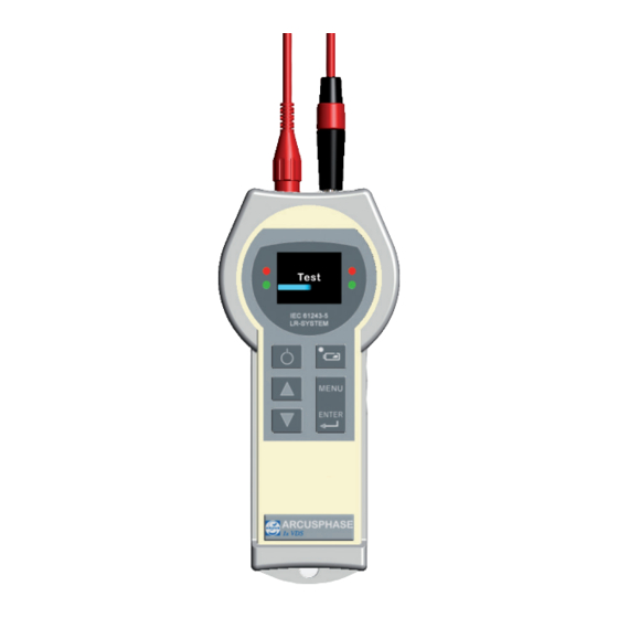
Description of voltage detector GA240GB-09.19 DESCRIPTION OF VOLTAGE DETECTOR Measurement line with plug for LR-system OLED-display Indication of measured values LED (green/red) Status indication of tests and measurements ON/OFF button LED (blue) Battery status Navigation button Test sockets for self-test with interface adaptor Menu-/Enter-button Test sockets... -
Page 10: Unpacking And Examination
! If shipment is packed orderly and parts are damaged or missing, please contact ARCUS Schiffmann. Recommendation ! Stock all packing material to be available in case the ARCUSPHASE DSP needs to be returned to ARCUS Schiffmann. -
Page 11: Start Of Operation
Your ARCUSPHASE DSP is equipped with a removable measuring line (for fast exchange at the location). For use with ARCUSPHASE DSP, only use a measuring line supplied by ARCUS Schiffmann! A damaged measuring line has to be exchanged (Spare parts and accessories → page 47)! -
Page 12: Automatic Switch-Off
GA240GB-09.19 Automatic switch-off AUTOMATIC SWITCH-OFF If no button is pressed or no measurement is carried out for 2 min in operating status, ARCUSPHASE DSP automatic switch-off will be activated. When in measurement mode current L1 the test result is “residual voltage present“... - Page 13 Symbols GA240GB-09.19 ARCUSPHASE DSP in measurement mode Frequency: Attention: > 51 Hz or f < 49 Hz ARCUSPHASE DSP in measurement mode Periodic testing: In order: Voltage is present and coupling operates faultlessly! ARCUSPHASE DSP in measurement mode Frequency: In order: <...
-
Page 14: Menu Navigation
GA240GB-09.19 Menu navigation Battery charge condition: 20 % Mode for LRP-interface is active. Mode for LRM- or LR-interface is active Mode for HR-interface is active MENU NAVIGATION Your ARCUSPHASE DSP is equipped with 2 menus, the main menu and the menu measurement mode. - Page 15 Menu navigation GA240GB-09.19 Instrument information: Indicates the version of the firmware and the date for the next periodic testing. Here one can leave the main menu and return to Back: measurement mode. Measurement mode: Messmodus Measurement mode To open the menu measurement mode, press one of Current L1 both navigation buttons.
- Page 16 GA240GB-09.19 Menu navigation Menu navigation - overview Uo/Un settings Main Menu 20/20 kV Uo/Un settings 10/20 kV Settings Manual Instrument information Back Back Settings Loudspeaker Language Clock settings Back Instrument information Measurement mode Current L1 Frequency L1 Oscilloscope Back...
-
Page 17: Indication Battery Status
Indication battery status GA240GB-09.19 INDICATION BATTERY STATUS When the LED (1) for battery state flashes, and the display shows a yellow battery symbol (2), battery should soon be exchanged (Battery change → page 48-49). Indication display Indication LED-battery status Battery status No indication. - Page 18 Measurement with a wrong interface adaptor on a connection can damage the ARCUSPHASE DSP and may lead to personal injuries! Only use accessories supplied by ARCUS Schiffmann! Maintain the ARCUSPHASE DSP well! Only remove the protector for battery exchange (→ page 48-49)! It protects the detector from mechanical damage.
-
Page 19: Self-Test Without Interface Adaptor
Self-test without interface adaptor GA240GB-09.19 SELF-TEST WITHOUT INTERFACE ADAPTOR Information ! During self-test of ARCUSPHASE DSP, the user is to observe faultless function of LEDs as they are not included in the self-test! Fit the measuring line into the test socket until it catches, as shown. Press the ON/OFF button to start the self-test of ARCUSPHASE DSP. - Page 20 GA240GB-09.19 Self-test without interface adaptor The self-test of ARCUSPHASE DSP includes Measurement line the measurement line L1. The indication on the left shows that during self-test a problem with the measurement line has occurred. Make sure that the measurement line is completely plugged into the measurement socket.
-
Page 21: Self-Test With Hr-Adaptor
Plug the measurement line into the HR-Adaptor until it locks, then plug the adaptor into the test socket at the right side of the detector until stop. Press the ON/OFF button to start the self-test of ARCUS- PHASE DSP. Automatic self-test is performed... - Page 22 GA240GB-09.19 Self-test with HR-adaptor After successful self-test, the detector automatically changes to measure- ment mode for measurement channel L1, and is ready to operate. After self-test, remove measuring line and the HR-adaptor from the test sockets. The self-test of ARCUSPHASE DSP includes Measurement line measurement lines L1 and the HR-adaptor.
-
Page 23: Self-Test With Lrm-Adaptor
Plug the measurement line into the HR-Adaptor until it locks, then plug the adaptor into the test socket at the right side of the detector until stop. Press the ON/OFF button to start the self-test of ARCUS- PHASE DSP. Automatic self-test is performed... - Page 24 GA240GB-09.19 Self-test with LRM-adaptorr After successful self-test, the detector automatically changes to measure- ment mode for measurement channel L1, and is ready to operate. After self-test, remove measuring line and the LRM-adaptor from the test sockets. The self-test of ARCUSPHASE DSP includes Measurement line measurement lines L1 and the LRM-adaptor.
-
Page 25: Self-Test With Lrp-Adaptor
Plug the measurement line into the LRP-Adaptor until it locks, then plug the adaptor into the test socket at the right side of the detector until stop. Press the ON/OFF button to start the self-test of ARCUS- PHASE DSP. Automatic self-test is performed... - Page 26 GA240GB-09.19 Self-test with LRM-adaptor After successful self-test, the detector automatically changes to measure- ment mode for measurement channel L1, and is ready to operate. After self-test, remove measuring line and the LRP-adaptor from the test sockets. The self-test of ARCUSPHASE DSP includes Measurement line measurement lines L1 and the LRP-adaptor.
-
Page 27: Connection Of Arcusphase Dsp To Coupling Part
Connection of ARCUSPHASE DSP to the coupling part GA240GB-09.19 CONNECTION OF ARCUSPHASE DSP TO THE COUPLING PART After successful self-test, a number of different tests and measurements can be performed on following coupling parts according to IEC 61243-5: LR-system: Plug measurement lines directly into sockets of coupling parts. HR-system: Consult instruction for use supplied with adaptor for correct usage (Spare parts and accessories →... - Page 28 GA240GB-09.19 Periodic testing of coupling parts and voltage test ARCUSPHASE DSP configuration for measurement channel L1. After successful self-test connect the red measurement line (L1) to coupling connection L1. Activate the menu measurement mode by pressing one of the two navigation-buttons. Messmodus Scroll through the navigation button to menu Measurement mode...
- Page 29 Periodic testing of coupling parts and voltage test GA240GB-09.19 Residual voltage present When the lower LED flash green, the ATTENTION-symbol and L1 with crossed- out voltage-symbol appear, then residual voltage is present. Interface current I is < 2.0 µA but ≥ 0.3 µA. Automatic switch-off of detector will be activated after 2 min.
-
Page 31: Frequency Measurement
Frequency measurement GA240GB-09.19 In general: Indication VOLTAGE PRESENT needs to appear: - in three-phase power networks within a conductor-earth voltage range of 45 % up to 120 % of the nominal voltage. Indication VOLTAGE PRESENT must not appear: - with conductor-earth voltage below 10 % of the nominal voltage In case it was impossible to perform phase comparison correctly, this will be shown on the display and by LED (Help in case of malfunction →... - Page 32 GA240GB-09.19 Frequency measurement Example of application: Frequency measurement at LR-, LRM-, HR-systems. Operating voltage Uo=20 kV, nominal voltage Un=20 kV, interface current I ≥ 3.2 µA, measuring channel L1 Activate the menu Measurement Mode by pressing a navigation-button. Messmodus Scroll through the navigation buttons to menu Measurement mode point Frequency L1 and confirm the selection Current L1...
-
Page 33: Oscilloscope
Oscilloscope GA240GB-09.19 Signalisation Frequency [Hz] Description 49 < f < 51 Interface and frequency are ok. The LED on the top shine red. 45 < f ≤ 49 Interface is ok, frequency faulty. 51 ≤ f ≤ 55 The top LED shine red. 0 ≤... - Page 34 GA240GB-09.19 Oscilloscope Information ! The function “Oscilloscope“ is possible only when the interface current for L1 fulfills the following conditions: LR-, LRM-, HR-System: Uo/Un=20kV/20kV I ≥ 3.2 µA Uo/Un=10kV/20kV I ≥ 1.6 µA manual/manual I ≥ 3.2 x (Uo/Un) LRP-System: Uo/Un=20kV/20kV I ≥...
-
Page 35: Fft
GA240GB-09.19 Fundamental frequency 50 Hz. Fundamental frequency 50 Hz with superposed harmonic (150 Hz). Function FFT (Fast Fourier Transform) shows you the spectrum of available frequencies. The vertical axis is linear. Information ! Function FFT is possible only when the interface current of L1 fulfills the following conditions: LR-, LRM-, HR-System:... - Page 36 GA240GB-09.19 After successful self-test connect red measurement line L1 to connection L1 of the coupling part. Example of application: FFT at LR-, LRM-system. Operating voltage Uo=20 kV, nominal voltage Un=20 kV, interface current I ≥ 3.2 µA, measuring channel L1 Activate the menu Measurement Mode by pressing a navigation-button.
-
Page 37: Configuration Of Operating And Nominal Voltage
Configuration of operating and nominal voltage GA240GB-09.19 CONFIGURATION OF OPERATING AND NOMINAL VOLTAGE After successful self-test it is possible to set up the operating and nominal voltage of the switchgear to be tested. In this process it is possible to set up pre-configured values or user-defined values. - Page 38 Configuration of operating and nominal voltage GA240GB-09.19 CONFIGURATION OF OPERATING AND NOMINAL VOLTAGE (CONTINUED) Configuration of preset values for operating and nominal voltage Messmodus Scroll through the navigation buttons to the Uo/Un settings menu point with the suitable presetting, and 20/20 kV confirm the selection with the MENU/ENTER- 10/20 kV...
- Page 39 Configuration of operating and nominal voltage GA240GB-09.19 CONFIGURATION OF OPERATING AND NOMINAL VOLTAGE (CONTINUED) Configuration of user-defined values for operating and nominal voltage. By pressing the Menu/Enter-button, the cursor Manual jumps to the next position. When the cursor has reached the final positi- on, re-pressing the Menu/Enter-button causes change of the cursor to the first position.
-
Page 40: Language Selection
GA240GB-09.19 Language selection LANGUAGE SELECTION On your ARCUSPHASE DSP you can adjust the language for the display texts. This adjustment at the same time has an effect on the format for the dividers used, for instance number formats (dot instead of comma). Konfiguration of language selection. -
Page 41: Switch-On Or Switch-Off Button Sound
Switch-on or switch-off button sound GA240GB-09.19 ARCUSPHASE DSP will save your selection Your selection remains saved after switching off the ARCUSPHASE DSP. SWITCH-ON OR SWITCH-OFF BUTTON SOUND For best perception of button entries and warnings you can switch on button and warning sounds on your ARCUSPHASE DSP. - Page 42 GA240GB-09.19 Switch-on or switch-off button sound By pressing of Menu-/Enter-button you Messmodus Settings confirm your selection.. Loudspeaker Language Clock set Back With this indication, the button and warning Loudspeaker sound of your ARCUSPHASE DSP are switched off. The soundless mode is indicated by the red symbol and OFF is selected.
-
Page 43: Setting Date And Time
Date and time setting GA240GB-09.19 DATE AND TIME SETTINGS You can set the date and time on your ARCUSPHASE DSP. Konfiguration of date and time. Activate the main menu after successful self-test by pressing the MENU/ENTER- button. Messmodus Scroll through the navigation buttons to menu Main menu point Settings, and confirm the selection with Uo/Un settings... -
Page 44: Help In Case Of Malfunction
ARCUSPHASE DSP. HELP IN CASE OF MALFUNCTION In case of malfunction please only change battery! Repair of electronics or of mechanic damages is to be effected by ARCUS Schiffmann only! Error/Fault OLED-Display Possible reason Remedy No indication. Batteries are empty. - Page 45 Despite exchanged mea- Electronics defect. Return ARCUSPHASE DSP to surement line, indication: ARCUS Schiffmann. No L1 defect guarantee when electronics was interfered with. Electronics defect. Return ARCUSPHASE DSP to Electronic ARCUS Schiffmann. No guarantee when electronics was interfered with.
-
Page 46: Routine Maintenance And Upkeep
Possible reason Remedy Red or green LED at the LED is defect. Return ARCUSPHASE DSP to side of LED-display does ARCUS Schiffmann. No not work. guarantee when electronics was interfered with. LED indication of battery Electronics defect. Return ARCUSPHASE DSP to state shines despite ARCUS Schiffmann. -
Page 47: Spare Parts And Accessories
Spare parts and accessories GA240GB-09.19 SPARE PARTS AND ACCESSORIES Carrying bag Protector Plastic case Outer dimensions[WxHxD]: Material: Lifoflex ® Outer dimensions[WxHxD]: 250 x 130 x 80 mm Type No. 610 400 03 395 x 295 x 106 mm Type No. 615 098 Type No. -
Page 48: Change Of Battery
GA240GB-09.19 Spare parts and accessories Change of batteries As the power consumption of batteries or rechargeable batteries is dependent on a number of factors, it is impossible to specify an exact lifetime. For reasons of better readability, the procedure described below is valid for batteries and for rechargeable batteries as well. -
Page 49: Waste Disposal
Old and used batteries are hazardous waste! Do not dispose in domestic waste but e.g. into a collection point. WASTE DISPOSAL Observe local regulations for disposal of ARCUSPHASE DSP and packing. ARCUS Schiffmann will not be reliable for unsuitable disposal. For queries concerning used materials please contact ARCUS Schiffmann. -
Page 50: Technical Data
GA240GB-09.19 Technical data TECHNICAL DATA Nominal frequency: 50 Hz Threshold value: 4.5 V at 2.0 MOhm Environmental temperature -20 °C up to +60 °C Protection class: IP 54 Usage: Indoor and outdoor Battery type: 3 x Alkali Mangan size LR6 or AA - 1.5 V or 3 x Lithium size FR6 or AA - 1.5 V or 3 x Mignon AA rechargeable battery size HR6 -1.2V Standard:... - Page 52 Phone General +49 (0) 89 / 436 04-0 General +49 (0) 89 / 431 68 88 Sales Department +49 (0) 89 / 436 04 73 Internet www.ARCUS-Schiffmann.com info@ARCUS-Schiffmann.com Seat of the Company Truderinger Str.199 D-81673 Munich...
Need help?
Do you have a question about the ARCUSPHASE DSP 1x VDS and is the answer not in the manual?
Questions and answers