Table of Contents
Advertisement
Quick Links
Switcher Assembly guide
Safety warning
The kits are main powered and use potentially lethal voltages. Under no circumstance should someone undertake the
realisation of a kit unless he has full knowledge about safely handling main powered devices.
Please read the "DIY guide" before beginning.
Print or open the following documents :
• Switcher2 or Switcher3 Schematics
• Switcher2 or Switcher3 Components layout
• Switcher2 or Switcher3 Parts list
Follow this guide from item number 1 till the end, in this order. The assembly order is based on components height, from
low to high profile, in order to ease the soldering process : The component you are soldering is always taller than the
previously assembled ones and it is pressing nicely against the work area foam.
Switcher Assembly guide
1.
Soldering
All the PCB holes are metallized. It means the connection between the top and bottom pads is already
done. The parts must be soldered only from below (unless differently stated).
Use only small diameter solder, 0.5 or 0.7 mm, 1mm maximum. Use the minimum possible amount of
solder. Bad joints are almost always caused by too much solder.
Here are two excellent introduction to soldering videos:
http://www.eevblog.com/2011/06/19/eevblog-180-soldering-tutorial-part-1-tools/
http://www.eevblog.com/2011/07/02/eevblog-183-soldering-tutorial-part-2/
2.
Switcher3 vs Switcher2
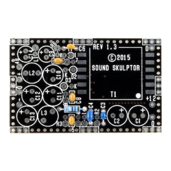
Switcher-3 is the full version with 3 outputs: +19V, -19V and +55V.
Switcher-2 is almost the same but with 2 outputs only: +19V, -19V.
This document describes the build of a Switcher-3. To build a switcher-2, simply omit C6 (ceramic), C9,
C14 (electrolytics), R6, L1 (axial inductor) and D1.
3.
PCB split
Split the multiple PCB along the red line on the picture.
This will separate the main PCB from the shielding cover.
Clean up the break line with very thin sand paper.
Copyright ©2015 to Today SoundSkulptor
www.soundskulptor.com
Last modification : 18/07/17
Advertisement
Table of Contents

Summary of Contents for Sound Skulptor Switcher
- Page 1 Switcher-3 is the full version with 3 outputs: +19V, -19V and +55V. Switcher-2 is almost the same but with 2 outputs only: +19V, -19V. This document describes the build of a Switcher-3. To build a switcher-2, simply omit C6 (ceramic), C9, C14 (electrolytics), R6, L1 (axial inductor) and D1.
- Page 2 Last modification : 18/07/17 Switcher Assembly guide R5 and Ceramic capacitors Add R5. Add C3, C4, C5, C6, C7, C8. Resistors Add R1 to R4, R6 to R8. These resistors are installed vertically. Warning : It is very important to check the resistors value with a DMM because the colour code can be ambiguous.
- Page 3 Last modification : 18/07/17 Switcher Assembly guide Transformer soldering Apply a small quantity of solder on one of the transformer PCB pads. Position the transformer, making sure the dot is in the correct place and reflow the pad solder to lock the transformer. Adjust until all the transformer pins are all well centred on their respective pad.
- Page 4 17. Shield (2) Insert delicately the 24 pins rows into the 3 pins socket on the switcher PCB, taking care not to bend any pin. Place the lid on top and solder the pins to the lid. Remove the lid.
- Page 5 4mm. 19. Switcher Quick testing The switcher can be tested directly in the final device but it is a good idea to check it alone if you can. What you need is a 12V DC source and a voltmeter.
Need help?
Do you have a question about the Switcher and is the answer not in the manual?
Questions and answers