
Related Manuals for MAGNOVENT FR3-43


Summary of Contents for MAGNOVENT FR3-43
- Page 1 INSTALLATION GUIDE International edition 2019/07 MAGN O VENT ® B U I L D I N G E F F I C I E N C Y...
- Page 2 AEIM03AE - © MAGNOVENT, S.L. ® All rights reserved. July 2020. The technical documenta�on is updated periodically. MAGNOVENT, S.L. reserves the right to modify all or part of the contents of this manual without prior no�ce.
-
Page 3: Important Information
Important information - Please read befo re attempting installation This fan must be installed by a licensed and quali ed 1. Please read these instructions carefully, be mindful of all warnings and safety information shown throughout this manual. Should you have any questions please call your local agent. 2. -
Page 4: Table Of Contents
Contents Important Information ..........................1 Content s ..............................Unpacking your Fa n ..........................3 Installing your Fan ........................... . 4 Option A - LED Light Ki t ......................... 10 Option B - Ceiling Extensio n Kit ...................... -
Page 5: Unpacking Your Fan
Unpacking your fan Unpack your fan and examine all parts, you should have the following: CEILING SPACER x 2 TIMBER SCREWS X 2 HANGER BRACKET MACHINE SCREWS X 2 WASHER X 2 WASHER X 2 HUB SCREWS X 10 MOTOR ASSEMBLY PIVOT LOCK X1 CONTROL RECEIVER AAA BATTERIES x2... -
Page 6: Installing Your Fan
Mounting Hanger Bracket to Ceiling STEP 1 supply at the main pow by removing fuse or tu OPTION B: OPTION A: Embedded Ceiling Joist hanger provided. Ensure ceiling joists are sound and of adequate size and strength to support a 35Kg (77lbs) load. If a between two beams.Proper care must be and stronger screws. - Page 7 Inserting otor into Hanger B racket STEP 3 Ensure that lug on Hanger is engaged in slot in suspension Ball Installing R eceiver into Hanger B racket STEP 4 Slide Remote Control Receiver into Hanger Bracket from the opposite side of the Terminal block Learn Switch Switch to “O”...
- Page 8 Connecting the Receiver STEP 5 Connect the 3PIN & Earth cable connector between DC Motor and Receiver. Connect the 3PIN connector between Mains Power and Reciever. 2PIN LED driver connection 3PIN (optional for LED Light) Aerial 3PIN Receiver to Motor 3PIN Mains Power to Receiver Earth Cable...
- Page 9 Pairing the Remote Control STEP 6 Pairing is always required during Note: “Learn” switch on receiver (STEP 4) Pairing a Single Fan per remote control: LEARN MODE NOTE: 1. On Receiver: Verify that the “Learn” switch is in the “O” LEARN BUTTON &...
- Page 10 Attaching the Fan Motor Housing STEP 7 CLICK! Align the 3 tabs with the 3 holes on the Housing and move upwards. Push tabs inwards slightly before sliding upwards Assembling the Fan Blades STEP 8 avoid damaging the fan/surface screws for each Blade. Place the Hub Upper onto a clean working area.
- Page 11 Assembling the Fan Blades cont. STEP Light Hub Lower (OPTIONAL) Fasten the the Hub Lower from the top side Lower) into the recess. With care, turn the fan using the 3 Hub Screws. over. Attaching the Fan Blades STEP 9 Pivot Connector Silicone Ring Lock Screw...
-
Page 12: Option Aled Light Kit
LED Light Kit OPTION A Line up the 2 pins on the LED light with the 2 Holes in the LED LIGHT Safety clip is engaged. Re-check the correct assembly by gently pulling on the Ceiling Extension Kit OPTION B Suitable for Raked Ceiling up to 15 “B”... -
Page 13: Option C Raked Ceiling Kit
Raked Ceiling Kit OPTION C “a” “B” “a” Angle “C” Clearance “B” Extension Rod Length Accessories Required 15° - 17° 200mm min. 115mm Rod (4 Included 17/32” 17° - 33° 200mm min. 600mm Rod (23 Not Included 5/8” 33° - 40° 900mm Rod (35 Not Included 7/16”... -
Page 14: Technical Speci Catio N
FR3 60” = . kg (1 . lbs) White/Silver/Black Dark/Light wood-grain Remote Control: Hand held, RF Wall switch control MODEL SPEED 1 SPEED 2 SPEED 3 SPEED 4 SPEED 5 SPEED 6 FR3-43 70rpm/4.5W 99rpm/6W 126rpm/8.4W 151rpm/11.3W 181rpm/15W 207rpm/20W FR3-50 57rpm/4.4W 93rpm/9.3W 122rpm/11W 142rpm/15W 160rpm/20.4W 180rpm/26.2W... -
Page 15: Care And Cleanin G
Ca re and Cleaning Regular cleaning of the Aeratron Ceiling fan blades and fan motor housing is the only maintenance needed. Due to the self-balancing design, a large build up of dust on blades may create an imbalance in extreme cases only, causing the blades to wobble during use. -
Page 16: General Information
General Information 1. All electrical motors, including fan motors generate some noise, and may feel hot to the touch. This is NOT a fault. Aeratron fan is mounted securely on a metal Hanger Bracket with rubber cushioning and a ball joint to are exactly the same - some may move more than others. -
Page 17: Transfer Of Warranty
Warranty Cont. Transfer of Warranty. If the dwelling where the fan is installed changes hands, the balance of the warranty passes to the new owner, providing the original bill of sale for the product is retained by the new owner. Warranty does not cover damage to the fan if it is moved from one dwelling to another during the warranty period. -
Page 18: Aeratron Ceiling Fan Warranty Details
Warranty Details WARRANTY PHONE NUMBER AUSTRALIA 1300 116 305 (9am to 5pm EAST) or please go to www.aeratron.com/contact model and colour of the fan. The installing electrician’s details may also be required. Aeratron ceiling fan warranty details Please File with your Purchase Receipt Customer Details Name;... - Page 19 HEADQUARTERS SOCIAL MEDIA P.E. Táctica | c/ Maña, 32 46980 Paterna @MagnoventClimateSolutions (Valencia) Spain @Magnovent +34 96 134 12 24 | info@magnovent.eu Magnovent www.magnovent.eu...
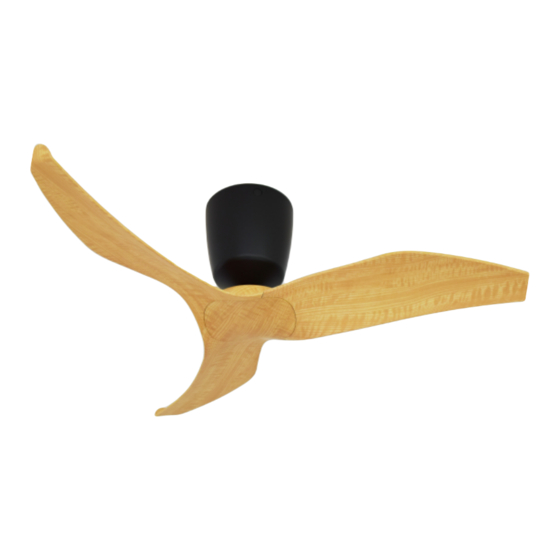
- Page 20 “As much as we sould like to take full credit for the desich of your Aeratron fan, we need to admit, we weren' t the first to think of it. The profile of the Aeratron blade and the winglet at its end reduce turbulence, providing more airflow with less energy, siletly.
Need help?
Do you have a question about the FR3-43 and is the answer not in the manual?
Questions and answers