Advertisement
Quick Links
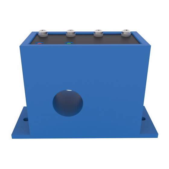
CurrentWatch™ EGF Series Ground Fault Sensors
IN ORDER TO AVOID ELECTRIC SHOCK OR OTHER POSSIBLE INJURY:
• DO NOT USE THIS PRODUCT FOR HUMAN SAFETY APPLICATIONS.
IT WAS NOT DESIGNED, TESTED OR RECOMMENDED FOR THIS
USE.
• DO NOT USE THIS PRODUCT IN HAZARDOUS LOCATIONS (E.G.
EXPLOSIVE ATMOSPHERES). IT WAS NOT DESIGNED, TESTED OR
RECOMMENDED FOR THIS USE.
• ENSURE THE PRODUCT IS PROPERLY WIRED TO THE CORRECT
POWER SUPLLY FOR THE APPLICATION. REFER TO THE
SPECIFICATIONS AND WIRING DIAGRAMS IN THIS MANUAL.
MODELS COVERED IN THIS MANUAL
Catalog Number
Description
EGF1NOACNE050
N.O. 1A @ 240V AC, Normally Energized, 50 mA Range
EGF1NOACDE050
N.O. 1A @ 240V AC, Normally De-Energized, 50 mA Range
EGF1NCACNE050
N.C. 1A @ 240V AC, Normally Energized, 50 mA Range
EGF1NCACDE050
N.C. 1A @ 240V AC, Normally De-Energized, 50 mA Range
EGF1NOACNE100
N.O. 1A @ 240V AC, Normally Energized, 100 mA Range
EGF1NOACDE100
N.O. 1A @ 240V AC, Normally De-Energized, 100 mA Range
EGF1NCACNE100
N.C. 1A @ 240V AC, Normally Energized, 100 mA Range
EGF1NCACDE100
N.C. 1A @ 240V AC, Normally De-Energized, 100 mA Range
EGF1NODCNE050
N.O. 0.15A @ 30V DC, Normally Energized, 50 mA Range
EGF1NODCDE050
N.O. 0.15A @ 30V DC, Normally De-Energized, 50 mA Range
EGF1NCDCNE050
N.C. 0.15A @ 30V DC, Normally Energized, 50 mA Range
EGF1NCDCDE050
N.C. 0.15A @ 30V DC, Normally De-Energized, 50 mA Range
EGF1NODCNE100
N.O. 0.15A @ 30V DC, Normally Energized, 100 mA Range
EGF1NODCDE100
N.O. 0.15A @ 30V DC, Normally De-Energized, 100 mA Range
EGF1NCDCNE100
N.C. 0.15A @ 30V DC, Normally Energized, 100 mA Range
EGF1NCDCDE100
N.C. 0.15A @ 30V DC, Normally De-Energized, 100 mA Range
EGF3NOACNET3
N.O. 1A @ 240V AC, Normally Energized, 5/10/30 mA Range
EGF3NOACDET3
N.O. 1A @ 240V AC, Normally De-Energized, 5/10/30 mA Range
EGF3NODCNET3
N.O. 0.15A @ 30V DC, Normally Energized, 5/10/30 mA Range
EGF3NODCDET3
N.O. 0.15A @ 30V DC, Normally De-Energized, 5/10/30 mA Range
EGF3NCACNET3
N.C. 1A @ 240V AC, Normally Energized, 5/10/30 mA Range
EGF3NCACDET3
N.C. 1A @ 240V AC, Normally De-Energized, 5/10/30 mA Range
EGF3NCDCNET3
N.C. 0.15A @ 30V DC, Normally Energized, 5/10/30 mA Range
EGF3NCDCDET3
N.C. 0.15A @ 30V DC, Normally De-Energized, 5/10/30 mA Range
Effective: August 2007
Installation Instructions
120V AC Powered, N.O. or N.C., Solid State Relay Output
WARNING
Questions? Call our Sensor Application Engineers at (800) 426-9184.
INTRODUCTION
The CurrentWatch™ EGF Series is a family of ground fault (earth
leakage) sensors. Ground fault sensors help protect people, products,
and processes from damage by ground fault conditions by monitoring
all current-carrying conductors in grounded single- and three-phase
delta or wye systems. They provide a contact output that can operate
relays, contactors or signal automation systems.
Note that this manual only covers solid state versions of the EGF
Series (listed in the table to the left). For installation manuals
covering other models in the EGF Series family, please contact
Eaton's Cutler-Hammer Sensor Application Engineers.
QUICK INSTALL GUIDE
The below steps can be followed to quickly install a CurrentWatch™
EGF Series switch.
1. Run all current carrying conductors through sensor window, using
an auxiliary current transformer if conductors do not fi t
2. Mount the sensor to a surface if needed
3. Connect output and power wiring
a. Use up to 14 AWG copper wires
b. Ensure power and load matches those shown on the sensor
label
4. Test the unit
a. Pressing the "TEST" button will test the sensor's internal
circuits (CAUTION: The output and any connected loads will
switch during the test process)
INSTALLATION AND WIRING
Considerations for installing and wiring EGF Series sensors...
• Run wire to be monitored through the aperture (opening) in the
switch body, making sure all wires are oriented so that current
fl ows in the same direction (see "Principal of Operation" section
on reverse side)
• These sensors can be located in the same environment as motors,
contactors, heaters, pull-boxes and other electrical enclosures
• Mounting can be done in any position or hung directly on a wire
with a wire tie
• Be sure to leave at least one inch distance between sensor and
other magnetic devices
• Connect power and output wiring to the sensor, using up to 14
AWG copper wire and tightening terminals to 7 inch-pounds torque
• Make sure the power supply matches the power rating on the
sensor label
• Make sure the output load is less than or equal to the output rating
on the sensor label
Control Power
(Match Sensor Rating--See Label)
Power
Setpoint Adjust
X
Factory Calibrated and Covered
G
(Remove Cover, Adjust and
Relabel if Required)
Power Supply LED
P51925 Rev 02
Load
Contactor, Relay, Shunt Trip Breaker...
(Do Not Exceed Rating--See Label)
(+)
Output Power
(Match Sensor Rating--See Label)
(-)
For DC Output Versions...
Observe Polarity
Output
TEST
Contact Status LED
490020207
Page 1
Advertisement

Subscribe to Our Youtube Channel
Related Manuals for Eaton CurrentWatch EGF Series


Summary of Contents for Eaton CurrentWatch EGF Series
- Page 1 USE. covering other models in the EGF Series family, please contact • DO NOT USE THIS PRODUCT IN HAZARDOUS LOCATIONS (E.G. Eaton’s Cutler-Hammer Sensor Application Engineers. EXPLOSIVE ATMOSPHERES). IT WAS NOT DESIGNED, TESTED OR RECOMMENDED FOR THIS USE. QUICK INSTALL GUIDE •...
- Page 2 P51925 Rev 02 490020207 PRINCIPAL OF OPERATION POWER SUPPLY NOTES All low-current ground-fault sensors are sensitive devices that require Under normal conditions, the current in one wire of a two wire load is reasonable care in system design to avoid false trips caused by high equal in strength but opposite in sign to the current in other wire.
Need help?
Do you have a question about the CurrentWatch EGF Series and is the answer not in the manual?
Questions and answers