
Summary of Contents for RECO HX2 Series
- Page 1 Installation, Operation, NSTALLATION PERATION and Maintenance Manual AINTENANCE MANUAL...
-
Page 2: Table Of Contents
ABLE OF ONTENTS Introduction - Overview of the HX2 ........................1-1 Sales and Service Support ........................ 1-2 Key Features and Benefits of the HX2 ....................1-2 Materials of Construction ........................1-2 Flow, Pressure, and Temperature Ratings ..................1-2 Recommended Spare Parts ......................1-3 HX2 Rating Charts ........................... -
Page 3: Introduction
This Installation, Operation, and Maintenance (IOM) manual is current as of the date issued, and RECO USA reserves the right to update, modify, amend, or change the information contained herein at any time without prior notice and without obligation to notify owners of this product of such changes. -
Page 4: Sales And Service Support
• Main office ....803) 794-3360 • Main fax ....... (803) 791-3304 To order replacement parts, contact RECO USA or your local authorized RECO USA representative. Key Features and Benefits of the HX2 • The HX2 safety system includes a pressure/temperature (P/T) relief valve, solenoid- operated, fail-open dump valve, and an automatic fail-closed steam inlet control valve. -
Page 5: Recommended Spare Parts
1. For copper-nickel tubes, de-rate the copper tube ratings shown by 20%. 2. The ratings curves shown assume a tube bundle fouling factor of 0.00025 (hr. x ft x °F / BTU). 3. For applications with water as the heating source, contact RECO USA Sales Department. 1 - 3... - Page 6 1 - I HX2 S ECTION NTRODUCTION ERIES 1.7a Rating Charts for 40 °F to 120 °F Heating 40 F to 120 F - Single Wall Copper Tubes 40 °F to 120 °F Heating – Single Wall, ½” OD Copper Tubes 12030 10030 08030...
- Page 7 1 - I HX2 S ECTION NTRODUCTION ERIES Rating Charts for 100 °F Heating 40 F to 140 F - Single Wall Copper Tubes 40 °F to 140 °F Heating – Single Wall, ½” OD Copper Tubes 12030 10030 08036 08030 06036 06030...
-
Page 8: Hx2 Configuration And Ordering Code
⚫ 1.8a Sample Selection: The selected unit is a RECO USA HX2 series water heater model HX2-H-0836-SS-CU- DW-M horizontal water heater with 8” diameter x 36” long heating element, 316L stainless steel tank, ¾” copper double-wall tubes, and standard Modbus ®... -
Page 9: Shipment And Storage
ATER EATERS NSTALLATION The following guidelines must be followed when installing a HX2 series water heater. Failure to do so can result in faulty performance, field service / support charges, and/or voiding of the warranty. Installation, operation, and/or maintenance should only be performed by trained personnel knowledgeable in proper plumbing and electrical practices, and in particular should be thoroughly trained in working with high pressure steam systems. -
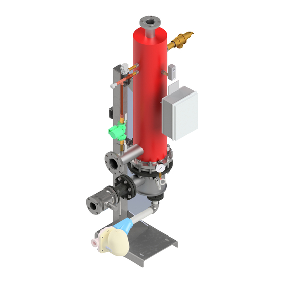
Page 10: Major Components Of The Hx2
2.2.12 An inlet steam strainer and steam trap immediately upstream of the inlet control valve (not provided by RECO USA) is necessary for optimal system performance. A condensate strainer and steam trap are provided loose as standard, with mounting and connection to be done in the field by others. -
Page 11: Factory Pre-Sets
2 - I HX2 S ECTION NSTALLATION ERIES 2.3.6 An electrically operated, fast-acting V-ball control valve is used to modulate flow of heating medium to the unit. It has a 100:1 rangeability which gives excellent control at all flow rates. Capacitors integrated into the actuator housing close the valve in the event of loss of power. -
Page 12: General Arrangement Dimensions And Weights - Vertical Units
2 - I HX2 S ECTION NSTALLATION ERIES 2.5 General Arrangement Dimensions and Weights – Vertical Units ABLE ERTICAL IMENSIONS Basic Size Wt. (lbs.) 06030 / 06036 2” 1 ½" 46.75 95.0 34.25 ¾ 24.0 17.75 1” FNPT / 1.25” FNPT 33.0 930 / 950 FNPT... -
Page 13: General Arrangement Dimensions And Weights - Horizontal Units
2 - I HX2 S ECTION NSTALLATION ERIES 2.6 General Arrangement Dimensions and Weights – Horizontal Units ABLE ORIZONTAL IMENSIONS Basic Size Wt. (lbs.) 06030 / 06036 2” 1 ½" 23.75 95.0 34.25 37.75 71.75 ¾ 1” / 1.25” FNPT 985 / 1,005 FNPT 08030 / 08036... - Page 14 2 - I HX2 S ECTION NSTALLATION ERIES HIS PAGE LEFT INTENTIONALLY BLANK 2 - 6...
-
Page 15: Operation
HX2 S ERIES NSTANTANEOUS ATER EATERS PERATION 3.1 Operating Instructions and Guidelines – Start Up Before starting, read this HX2 Installation, Operation, and Maintenance Manual (IOM) in its entirety prior to proceeding. The separate section on the Control Master operation (Appendix A) contains important information on pump on/off, and control valve open/close instructions that should be understood before starting the unit up. -
Page 16: Operating Instructions And Guidelines - Shut Down
IOM S 3- O HX2 S ECTION PERATION ERIES 3.2 Operating Instructions and Guidelines – Shut Down Before shutting the unit down, assure that hot water demand for the unit is not needed. The operator should also re-read this HX2 Installation, Operation, and Maintenance Manual (IOM) in its entirety prior to proceeding. -
Page 17: System Wiring Diagram
IOM S 3- O HX2 S ECTION PERATION ERIES 3.3 System Wiring Diagram - Sizes 0630 and 0636 3 - 3... - Page 18 IOM S 3- O HX2 S ECTION PERATION ERIES 3.4 System Wiring Diagram - Sizes 0830 Through 1236 3 - 4...
-
Page 19: Maintenance
NSTANTANEOUS ATER EATERS AINTENANCE 4.1 HX2 Series Maintenance Schedule Even under the best of conditions, some regular maintenance on the HX2 is needed. The table below is a general guide as to how often this should be done. ABLE ECOMMENDED... - Page 20 IOM S 4- M HX2 S ECTION AINTENANCE ERIES ABLE ROUBLESHOOTING IELD UIDE Likely Cause and Suggested Remedy Problem ⚫ ⚫ ⚫ ⚫ ⚫ ⚫ Unit fails to reach required outlet water temperature ⚫ ⚫ ⚫ ⚫ Outlet water temperature too high ⚫...
-
Page 21: Hx2 Tube Bundle Maintenance
IOM S 4- M HX2 S ECTION AINTENANCE ERIES its connection at the tube sheet has been compromised. The heating tube bundle will have to be removed, and cleaned or replaced. Follow the procedures given in Section 4.3 for this. 8 –... - Page 22 IOM S 4- M HX2 S ECTION AINTENANCE ERIES 4.3a HX2 Tube Bundle Inspection and Cleaning Examine the heat exchanger coil for signs of leaking or scale buildup on the tube surface. If there is no leaking detected, carefully clean any scale from the coil and prepare the coil for installation.
-
Page 23: Flange Bolt Tightening Sequence And Torque Values
IOM S 4- M HX2 S ECTION AINTENANCE ERIES 4.4 Flange Bolt Tightening Sequence and Torque Values The following bolt tightening pattern and torque values should be used whenever tightening a flange. A recommended practice is to do this in (3) steps leading up to the final torque values, rather than attempting to complete this in one sequence. -
Page 24: Circulator Pump Maintenance
IOM S 4- M HX2 S ECTION AINTENANCE ERIES 4.5 Circulator Pump Maintenance The HX2 is equipped with a circulator pump. This circulator should be inspected periodically per the following guideline. 4.5.1 Observe all applicable codes when connecting to power supply. The motor is impedance protected and does not require overload protection. -
Page 25: Control Valve Maintenance
IOM S 4- M HX2 S ECTION AINTENANCE ERIES 4.6.4 Remove the screen and clean it. Do not let the screen dry out, as it will be difficult to remove debris after it has hardened. Avoid banging or hitting the screen. Note that before removing the cover of the strainer, the pressure inside the tank must be released to bring it to atmospheric. - Page 26 IOM S 4- M HX2 S ECTION AINTENANCE ERIES a. To inspect and/or replace body seals, seats, packing, and/or ball, the valve must be in the open position with no flow through the valve and removed from pipeline. b. With the valve in the open position, undo the body bolts from the body nuts to remove the end caps from the body.
-
Page 27: Appendix 1 - The Control Master ® Control Panel
HX2 S ERIES NSTANTANEOUS ATER EATERS 1 – T PPENDIX ONTROL ASTER ONTROL ANEL A.1 General Operation The function of the controller is to maintain the water outlet temperature of the water heater and monitor its status. This is done with a PID control loop that sends a signal to the steam control valve. -
Page 28: Start Up Procedures
IOM A 1- T HX2 S PPENDIX ONTROL ANEL ERIES A.2 Start Up Procedures The control panel is preprogrammed with set points configured to the job conditions. By default, the circulating pump and control valve are disabled to prevent their immediate operation upon application of AC power to the panel. - Page 29 IOM A 1- T HX2 S PPENDIX ONTROL ANEL ERIES A.2.2 Control Valve - The controller has the ability to stroke the control valves manually. After factory testing, the MANUAL OVERRIDE is ENABLED and control valves are set to 0% to keeps the control valve closed. To open or close the control valve, follow the instructions below.
-
Page 30: Adjusting The Set Points
IOM A 1- T HX2 S PPENDIX ONTROL ANEL ERIES A.3 Adjusting the Set Points Step 1 - Access the OPER menu by using the down button to move the cursor to GO TO OPER MENU and press ENTER. Step 2 - To edit the set point move to EDIT SP and press ENTER. Step 3 - Use the SETPOINT TYPE to toggle between LOCAL or REMOTE. -
Page 31: Adjusting The Alarm Settings
IOM A 1- T HX2 S PPENDIX ONTROL ANEL ERIES A.4 Adjusting the Alarm Settings Step 1 - Access the SET UP menu by scrolling to the bottom of the main menu top PASSWORD HANDLING and press the ENTER key. Step 2 - Use the UP / DOWN buttons to enter the password 1709, pressing the ENTER key after each digit is entered, to access the Setup Menu. -
Page 32: Alarm Menu
IOM A 1- T HX2 S PPENDIX ONTROL ANEL ERIES Step 5 – Press ENTER to bring up the HIGHTEMPALARM setpoint and dead band options. Press ENTER on the highlighted item to bring up the adjustment screen. Step 6 - Adjust UP or DOWN and press ENTER. -
Page 33: Fault Detection
IOM A 1- T HX2 S PPENDIX ONTROL ANEL ERIES Select one of the entries and press ENTER for more details. For example, the screen shot below shows the time and date that the high temp limit switch had tripped. The Control Master panel keeps a history log of these events. -
Page 34: Panel Box Layout And Component Listing
IOM A 1- T HX2 S PPENDIX ONTROL ANEL ERIES A.7 Panel Box Layout and Component Listing ABLE ANEL OMPONENT AYOUT Item Description Item Description Front panel 120 vac l1 (hot) connection HMI display Fuse block Internal panel 120 vac terminals 12”... -
Page 35: Panel Box Controller Connections
IOM A 1- T HX2 S PPENDIX ONTROL ANEL ERIES A.8 Panel Box Controller Connections ABLE ONTROLLER ONNECTIONS AND UNCTIONS Block Position Terminal Type Signal Description 100K Ohm Boiler Water Inlet Temp (n/a for Steam Fired) Common 100K Ohm Boiler Water Outlet Temp (n/a for Steam Fired) 1K Ohm Domestic Water Outlet Temp O-mA... - Page 36 IOM A 1- T HX2 S PPENDIX ONTROL ANEL ERIES Control Panel Display Menu Listings – Main Menu ABLE ISPLAY ISTINGS MAIN Menu Listing Description Limits / Values Control Signal Temperature Controller Output Setpoint Displays Current Set Point Deg F Water Temp Out Displays Current Water Outlet Temperature Deg F...
- Page 37 IOM A 1- T HX2 S PPENDIX ONTROL ANEL ERIES A.9b Control Panel Display Menu Listings – Configuration Menu ABLE ISPLAY ISTINGS CONFIG Menu Description Limits / Values Water Temp Out Displays Water Outlet Temp Deg F Water Temp Out Min Set Maximum Water Temp Range Deg F Water Temp Out Max...
- Page 38 IOM A 1- T HX2 S PPENDIX ONTROL ANEL ERIES A.9c Control Panel Display Menu Listings – Set Up Menu ABLE ISPLAY ISTINGS SET UP Menu Description Limits / Values Configure Setpoint Access for Set Point Functions Remote Enable Jumper Enables Heater Operation Proportional Factor Display of Proportional Gain Integral Factor...
- Page 39 IOM A 1- T HX2 S PPENDIX ONTROL ANEL ERIES HIS PAGE LEFT INTENTIONALLY BLANK A - 13...
- Page 40 © 2019 RECO USA. All Rights Reserved. All trademarks are the property of RECO USA, and unauthorized use of these trademarks, as well as the information presented herein, is expressly prohibited and constitutes a violation of the intellectual property rights of RECO USA.
Need help?
Do you have a question about the HX2 Series and is the answer not in the manual?
Questions and answers