Table of Contents
Advertisement
Quick Links
Advertisement
Table of Contents

Related Manuals for PureLink VIP-CAM-100-USB3

Summary of Contents for PureLink VIP-CAM-100-USB3
- Page 1 VIP-CAM-100-USB3 PTZ USB3 Camera with DVI Output USER MANUAL 22-10 State Route 208 Fair Lawn, NJ 07410 USA Tel: +1.201.488.3232 Fax: +1.201.621.6118 E-mail: sales@purelinkav.com For order support, please contact your local dealer. For technical support, please contact us at support@purelinkav.com.
-
Page 2: Table Of Contents
Bottom .................................. 6 DIP Switch settings (bottom of base) ........................ 6 Remote .................................. 7 Installation ................................8 Connecting to a Computer via USB 3.0 ......................... 8 Connections ................................8 RS-232 ................................... 8 8 ft. 8-pin Mini Din Male to DB9 Female RS-232 Cable Supplied with VIP-CAM-100-USB3 ......9 20-Meter 8-pin Mini Din Male to pigtail RS-232 Cable Wiring for VIP-CAM-100-USB3 ........10 VIP-CAM-CTRL1 RS-232 Connections ......................11 On-Screen Display (OSD) ............................12 Top Level Menu ..............................12 VIDEO Menu ................................ 12 EXPOSURE Menu ..............................13 WHITE BALANCE Menu ............................14 PAN TILT ZOOM Menu ............................15 SYSTEM Menu ..............................16 STATUS Menu ..............................16 RESTORE DEFAULTS Menu ..........................16 Resetting to Factory Default ........................... 17 Troubleshooting ..............................17 No Image ................................17 Warranty & Customer Service ..........................18 VIP-CAM-100-USB3 USER MANUAL VERSION 1.1... -
Page 3: Package Contents
Package Contents (1) VIP-CAM-100-USB3 Full HD PTZ Camera • (1) Remote control • (1) 100-240VAC to 12V DC power adapter • (1) RS232 cable – 9-pin D-Sub to 8-pin Mini Din • Optional Accessories VIP-CAM-100-USB3-WMNT • Metal bracket mount for wall installation VIP-CAM-100-USB3-CMNT • Metal bracket mount for inverted ceiling installation VIP-CAM-100-USB3 USER MANUAL VERSION 1.1... -
Page 4: Product Description
Pan speed variable from .1°/sec to 120°/sec • Tilt speed variable from .1°/sec to 90°/sec • DVI 1080P60 output • Precision PTZ drive system • VISCA, PELCO-D, PELCO-P control via RS-232/485, HTTP • Infrared remote control • Smart AE technology (Automatic Exposure) • Desktop/ceiling/wall mount options • Create/recall over 200 PTZ presets with remote control • DVI Video Output Formats 720P50 • 720P60 • 1080i50 • 1080i60 • 1080P25 • 1080P30 • 1080P50 • 1080P60 • VIP-CAM-100-USB3 USER MANUAL VERSION 1.1... -
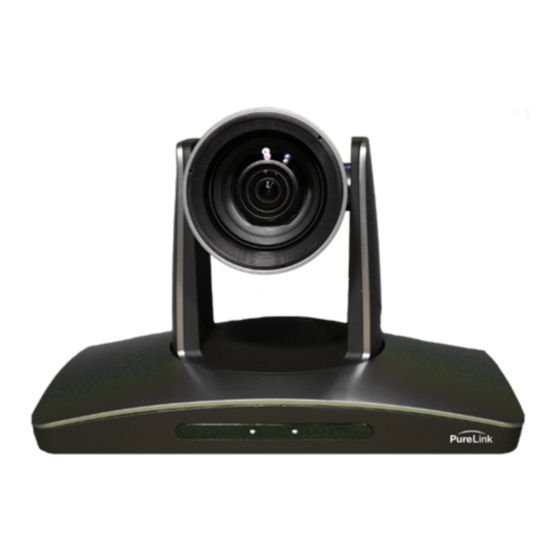
Page 5: Front
Front 1. 20x optics 2. IR receiver 3. Power LED indicator Rear Panel 1. USB 3.0 video output 2. DVI video output 3. RS232/485 in 4. RS232/485 out 5. 12VDC power port VIP-CAM-100-USB3 USER MANUAL VERSION 1.1... -
Page 6: Bottom
Bottom 1. Setup switches 2. ¼” mounting thread DIP Switch settings (bottom of base) Switch 1 (SW1) • Sets device address and mounting orientation Switch 2 (SW2) • Sets protocol type, baud rate, video output format See Appendix: DIP Switch Settings VIP-CAM-100-USB3 USER MANUAL VERSION 1.1... -
Page 7: Remote
12. Pattern Loop: Continuous Pan 5. Focus 13. Back Light: Open/close backlight a. Trigger Focus: Performs autofocus compensation when pressed. 14. Zoom: Performs zoom in or zoom out b. Focus Near/Far: Performs near focus or far focus 15. Iris: 6. Menu: Enter/exit OSD settings menu a. Reset iris to default 7. Directional Pad: Non-menu: controls pan b. Iris open or close and tilt. Menu: navigation 16. Back: Go back to previous menu 8. Data: Toggles PTZ data on screen Remote requires 2x AAA batteries. VIP-CAM-100-USB3 USER MANUAL VERSION 1.1... -
Page 8: Installation
Wall • Tripod/pendant • Connecting to a Computer via USB 3.0 The VIP-CAM-100-USB3 requires a USB 3.0 connection on your computer. Connections Power • Each VIP-CAM-100-USB3 can be powered from the included AC to 12VDC power adapter Video • Video will output on the following connections: USB 3.0: up to 1080P60 § DVI: up to 1080P60 § Infrared • The VIP-CAM-100-USB3 can be controlled with the included infrared remote control RS-232 • The VIP-CAM-100-USB3 system provides VISCA or PELCO control through an RS-232 connection RS-232 The VIP-CAM-100-USB3 uses an 8-pin Mini Din Female connector for incoming RS-232 control and loop out. Pin 3: TX (To controller) • Pin 4: GND • Pin 5: RX (From controller) • VIP-CAM-100-USB3 USER MANUAL VERSION 1.1... -
Page 9: Ft. 8-Pin Mini Din Male To Db9 Female Rs-232 Cable Supplied With Vip-Cam-100-Usb3
Information is provided below on using various cables with the camera. Please note when daisy-chaining cameras, you must use an 8-pin Mini Din Male to 8-pin Mini Din Male that is wired for crossover (pin 3 to 5, and pin 5 to 4). 8 ft. 8-pin Mini Din Male to DB9 Female RS-232 Cable Supplied with VIP-CAM-100-USB3 DB9-F to 8-pin Mini Din Male White – DB9 pin 2 (RXD) > Mini Din pin 3 Red – DB9 pin 3 (TXD) > Mini Din pin 5 Black – DB9 pin 5 (GND) > Mini Din pin 4 When using the PureLink VIP-CAM-CTRL1 controller with the VIP-CAM-100-USB3 cameras, the DB9 connector will need to be removed, as the controller uses a terminal block as shown below. VIP-CAM-100-USB3 USER MANUAL VERSION 1.1... -
Page 10: 20-Meter 8-Pin Mini Din Male To Pigtail Rs-232 Cable Wiring For Vip-Cam-100-Usb3
20-Meter 8-pin Mini Din Male to pigtail RS-232 Cable Wiring for VIP-CAM-100-USB3 Blue (RXD) Orange (TXD) Black (GND) Wiring below is shown with the PureLink VIP-CAM-CTRL1 terminal block. Wiring on the bottom of the image is from the controller. 8-pin Mini Din control cable YELLOW GREEN ORANGE 4 GND BLACK BLUE RED BROWN VIOLET VIP-CAM-100-USB3 USER MANUAL VERSION 1.1... -
Page 11: Vip-Cam-Ctrl1 Rs-232 Connections
VIP-CAM-CTRL1 RS-232 Connections The VIP-CAM-CTRL1 provides a connector header for the RS-232 wiring. GND WHITE • YELLOW (sent to camera) • GREEN (received from camera) • VIP-CAM-100-USB3 USER MANUAL VERSION 1.1... -
Page 12: On-Screen Display (Osd)
On-Screen Display (OSD) Top Level Menu <MENU> VIDEO EXPOSURE WHITE BALANCE PAN TILT ZOOM SYSTEM STATUS RESTORE DEFAULT VIDEO Menu VIP-CAM-100-USB3 USER MANUAL VERSION 1.1... -
Page 13: Exposure Menu
EXPOSURE Menu VIP-CAM-100-USB3 USER MANUAL VERSION 1.1... -
Page 14: White Balance Menu
WHITE BALANCE Menu VIP-CAM-100-USB3 USER MANUAL VERSION 1.1... -
Page 15: Pan Tilt Zoom Menu
PAN TILT ZOOM Menu VIP-CAM-100-USB3 USER MANUAL VERSION 1.1... -
Page 16: System Menu
SYSTEM Menu STATUS Menu RESTORE DEFAULTS Menu VIP-CAM-100-USB3 USER MANUAL VERSION 1.1... -
Page 17: Resetting To Factory Default
Resetting to Factory Default Factory default changes the following parameters: VISCA, ID 1 • Remote control ID, 1 • Exposure – Auto • White balance – Auto • Troubleshooting No Image Check power adapter is connected and is outputting 12VDC • Check output video cables • Check output resolution is set to an accepted resolution of the display • Check exposure level • VIP-CAM-100-USB3 USER MANUAL VERSION 1.1... -
Page 18: Warranty & Customer Service
Any implied warranties that may be imposed by law are limited to the terms of this limited warranty. This warranty statement supersedes all previous warranties. WARRANTY RETURNS/REPAIRS/EXCHANGES No merchandise may be returned without prior authorization from PureLink, and a Return Materials Authorization (RMA) number. Failure to comply with these conditions will result in rejection of the returned merchandise. Any warranty service on Products must be arranged through Dealer. Authorized returns must be shipped freight prepaid and fully insured to PureLink, Ramsey, NJ USA, with the RMA number clearly marked on the outside of all shipping boxes and containers. PureLink reserves the right at its sole discretion to refuse any shipments arriving freight collect or without an RMA number. Any authorized returned merchandise must be accompanied by a note describing the reason for return, along with contact information including name, phone number, return mailing and shipping addresses, e-mail address, and RMA number. - Page 19 Most problems can be corrected over the phone through close cooperation between Customer and a PureLink technician. To better enable PureLink to address a warranty claim, please have the Product’s serial and model numbers. If PureLink, in its sole discretion, determines that an on-site visit or other remedial action is necessary, PureLink may send a representative to Customer’s site.
Need help?
Do you have a question about the VIP-CAM-100-USB3 and is the answer not in the manual?
Questions and answers