
Related Manuals for Fbt QUBE SP27

Summary of Contents for Fbt QUBE SP27
- Page 1 QUBE SP27 - Audio Management System FBT ELETTRONICA S.p.A www.qubeaudio.com www.fbt.it...
- Page 3 SP 27 Quick Reference Editing channels : press channel's GAIN key. First press accesses that channel's gain. To scroll through channel's parameters, use the BACK NEXT keys. Second press accesses last viewed parameter. Third press will drop back to the default screen. Accessing menus: press the MENU...
-
Page 4: Table Of Contents
Contents Important Safety Information Unpacking the unit Introduction Features Front Panel Familiarisation Rear Panel Connections Operating the SP27 Note about operation with AudioCore software Start-up procedure Preliminary Set-up Input Channel Makeup Output Channel Makeup Preset Routing Configurations Free Assign Routing Input Gain Base Delay Input Parametric EQ... - Page 5 Security and Locking Entering the Password to Complete the Locking Operation Unlocking the Unit Forgotten the Password? Advanced Audio Features Program Limiter and “D-Max” Limiter Program Limiter “D-Max” Clip Limiter Setting Accurate Limiter Thresholds Crossover Filter Slopes TimeAlignment Parametric Filter Types and Their Uses Standard Parametric EQ Shelving EQ (High Shelf shown) Creating a Flat-topped EQ Response...
-
Page 6: Important Safety Information
An example of this equipment has been testedandfoundtocomplywiththefollowingEuropeanand internationalStandardsforElectromagneticCompatibilityandElectricalSafety: RadiatedEmissions(EU): EN55013-1(1996) RFImmunity(EU): EN55103-2(1996)RFImmunity,ESD, BurstTransient, Surge,Dips&Dwells ElectricalSafety(EU): EN60065(1993) Important Safety Information DonotremoveCovers. Nouserserviceablepartsinside, referservicingtoqualifiedservicepersonnel. Thisequipmentmustbeearthed. CAUTION RISK OF ELECTRIC SHOCK DO NOT OPEN DO NOT EXPOSE TO RAIN, MOISTURE, DRIPPING OR SPLASHING ATTENTION RISQUE DE CHOC ELECTRIQUE NE PAS ENLEVER... -
Page 7: Unpacking The Unit
Unpacking the unit After unpacking the unit, please check it carefully for any damage. If any is found, immediately notify the carrier concerned - you, the consignee, must instigate any claim. Please retain all packaging in case of future re- shipment. -
Page 8: Introduction
Introduction The SP27 are powerful DSP based audio processors, ideally suited for install applications, where they combine the functions of a multitude of conventional products in a compact 1U unit with extensive remote control capabilities. To achieve this, the units have up to four inputs and eight outputs which can be configured in a selection of basic crossover modes - 4 x 2 way;... -
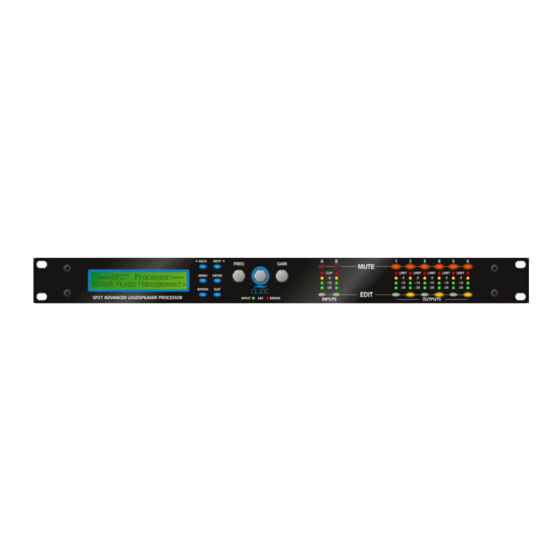
Page 9: Front Panel Familiarisation
Front Panel Familiarisation LCD Screen: Shows, by default, the name of the last recalled memory on the bottom line of the screen, and the current routing on the top line. Also used to show all parameters as they are edited, and all menu selections. Control Keys: Selection and adjustment of parameters. -
Page 10: Rear Panel Connections
Rear Panel Connections Power Switch: turns the unit's mains supply off and on. Mains Fuse: located in a finger-proof holder adjacent to the mains inlet. A spare fuse is also located in this holder. Mains Inlet: connected via a standard IEC socket. Always replace the fuse with the correct type and rating as shown on the rear panel legend. -
Page 11: Operating The Sp27
Operating the SP27 Note about operation with AudioCore software. The following operating information covers setup and control of the SP27 via the front panel controls only. Please consult the manual supplied with this software for information regarding full computer control. Start-up procedure Switching on the unit will display a brief message detailing the unit type and software version running == AudioCore DP4XX ==... -
Page 12: Input Channel Makeup
Routing Options and Processing Blocks Due to the completely new DSP platform, the routing possibilities within the SP27 have been made completely flexible, with a matrix available allowing any combination of inputs to be routed to any output. The additional DSP power has permitted the inclusion of more processing blocks, even considering the extra inputs and outputs, and the doubling of sample rate. - Page 13 2 x 3 way crossover 1 x 6 way crossover 2 x 2 way + mono...
-
Page 14: Free Assign Routing
Free Assign Routing If none of the preset configurations are appropriate to the required system setup, it is possible to manually select the routing of the crossover. This is achieved through the Crossover Menu -> Design A Crossover Pressing ENTER will start the crossover design wizard, with the first option being to choose the routing. -
Page 15: Input Gain
Editing Audio Parameters - Input Channels Input Gain The range of the control over the input gain is –40dB to +6dB in 0.1dB steps. I n A Input A Gain Input Gain = +6.0dB Gain Base Delay The maximum available delay between any input and output is 650.00mS. For example, if the input delay on channel A is set to 500mS, the maximum available output delay for any output fed from input A will be 150mS. -
Page 16: Output Gain
Editing Audio Parameters - Output Channels Output Gain The range of the control over the input gain is –40dB to +15dB in 0.1dB steps. Output1 Gain Output Gain = +6.0dB Gain Output Polarity The polarity (or phase) of each output may be switched individually as below. Output1 Polar Polarity = [+]... -
Page 17: Output High Pass Filter
Output High Pass Filter The high pass crossover filter on each output has a frequency range of <10Hz up to 32kHz in 1/36 Octave steps. If you try to set the high pass filter to a higher frequency than the low pass (which would be pointless and result in no output), the message High/Low Freq. -
Page 18: Output Limiter
Output Limiter The limiter on each output has adjustable attack and threshold, with a release time that is selectable to be a multiplier of the attack time. For example, as shown below, the attack time is 2mS and release is “x16” so 32mS. The attack and release times can be automatically linked to the high pass filter frequency, so that they are set to correct values for the output's frequency range. -
Page 19: Input Ganging And Output Ganging
Input Ganging and Output Ganging The method of linking inputs or outputs together during editing is achieved in the same way, so only crossover (output) ganging will be explained here. Having selected Crossover Ganging from the menu under the Crossover Sub-Menu, the current ganging set-up will be displayed. This will either be a preset selection as would be useful in a standard crossover configuration –... -
Page 20: Menu System Overview
Menu System Overview... - Page 21 Menu System Shortcuts A lot of functions have been assigned menu shortcuts – these are accessible directly from the default screen by pressing MENU followed by the appropriate MUTE EDIT button as shown. The entire list of features accessible in this way is given below. Store Graphic Memory...
-
Page 22: Menus In Detail
Menus in Detail GLOBAL MEM. Recall a Memory Recall , Input and Crossover Memories or combinations of. Store a Memory Store, Input and Crossover Memories or combinations of. Erase a Memory Erase, Input and Crossover Memories or combinations of. INPUT SECTION Input Ganging Gang (link) inputs together so their parameters track. -
Page 23: Memory Structure
Memory Structure As with the SP26 , the SP27 has its memory split into sections, allowing independent recall of crossover settings (i.e. all parameters associated with outputs), and input settings. Additionally, the graphic equaliser settings are stored in independent locations. There are, therefore, three types of memory available –... - Page 24 As only memory 8 and memory 10 have all 3 types stored, these will be the only numbers available during a recall. However, consider the example where the type of recall is set to Input & Crossover. In this instance, not only will the memory locations that have just Input and Crossover types stored be available, but the locations 8 &...
-
Page 25: Remote Control Interface Operation
Remote Control Interface Operation RS232 Interface This interface is fitted as standard to all units and is accessed via the 9-pin D-type connector on the rear of the unit. Note that to connect to a computer's COM (serial) port correctly, a one-to-one cable must be used, and NOT a 'null modem' cable. -
Page 26: Aes Inputs And Outputs
AES Inputs The SP27 Series units have a full AES implementation built in as standard. This allows the unit to receive digital audio directly. The switching of input can be performed independently, and the inclusion of sample rate converters on the inputs allows the unit to accept sample rates from 32kHz up to 192kHz. AES Input Input selection is via a recessed switch on the rear panel of the unit, between input B and output 1. -
Page 27: Aes Diagnostics And Status Information
AES Diagnostics and Status Information Also under the AES/EBU Sub Menu is the AES Status Information option, which can be used to check the incoming sample rate(s) and confirm that the data is being received correctly. Pressing ENTER will first show AES Device Status V1: E V2: E... -
Page 28: Security And Locking
Security and Locking After selecting the Security Sub Menu and pressing ENTER , select one of the lock types, choosing the most appropriate one for your application. As ever, ENTER will confirm your selection. User Specific Upon pressing ENTER to select this type of lock, each parameter group is presented in turn. Choose the type of lock (as above) using the FREQ encoder, and press... -
Page 29: Unlocking The Unit
Unlocking the Unit To unlock the unit press ENTER and then type the code in. This can be entered by using the FREQ control to select a character, and the BACK NEXT keys to move to the next character. Alternatively, the EDIT keys can be used to enter a code by pressing any combination of the eight buttons. -
Page 30: Advanced Audio Features
ADVANCED AUDIO FEATURES Program Limiter and “D-Max” Limiter The SP27 units have two levels of dynamic protection on its outputs – a traditional program limiter, and a newly introduced “D-Max” limiter. Program Limiter High performance digital limiters are provided for each output with control over attack time, release time and threshold parameters - see page for details. -
Page 31: D-Max" Clip Limiter
“D-Max” Clip Limiter The main limitation with traditional dynamics control is the inability of the processing to react truly instantaneously to the signal. One of the most significant advantages of digital signal processing over analogue is the ability to delay the audio signal precisely and without extensive complex hardware. The entire domain of digital signal processing is based around the combination of delaying, multiplying, and accumulating numbers (representing samples of audio) to implement all the filters and dynamics processing we have come to expect today. - Page 32 The SP27 “D-Max” limiter predelays the sidechain signal, resulting in a “zero overshoot” limiter, which is able to catch all peaks and provide a reliable absolute maximum setting for the output of any channel. The predelayed sidechain is shown in green, with the main signal in red.
-
Page 33: Setting Accurate Limiter Thresholds
Setting Accurate Limiter Thresholds The limiters built into the SP27 Series are intended to be used for loudspeaker driver protection, as opposed to amplifier protection. All modern professional power amplifiers designed for live sound use have their own limiters, which are tailored to protecting the amplifier from clipping. The following section describes how to set up the units' limiters to provide exceptional protection against driver overheating, and cone over-excursion. -
Page 34: Crossover Filter Slopes
Crossover Filter Slopes It should also be noted that the turnover frequency displayed on the screen is the -3dB point for all types except Linkwitz-Riley where the -6dB point is shown. If the -6dB point is to be used for the Bessel or Butterworth filter, take the required crossover frequency, multiply this by the appropriate factor from the following table and then select the closest available frequency on the display. -
Page 35: Parametric Filter Types And Their Uses
Parametric Filter Types and Their Uses A wide selection of filter types has been made available under the PEQ section when editing input or output filters. Scrolling through the various filter types is achieved by repeated presses of the ENTER key. Note that this will only change filter types if the filter is BYPASSED or the GAIN set to 0dB. -
Page 36: Shelving Eq (High Shelf Shown)
Shelving EQ (High Shelf shown) Input A HSF:1-<:: 1k00Hz Q=3.0 0.0dB Remember – to change filter types, press BYPASS to bypass the filter, and then use ENTER to select the filter type. The shelving EQ has adjustable frequency, 'Q' (or Bandwidth) and Gain controls. -
Page 37: Low/High Pass Variable "Q" Filter (Low Pass Shown)
Low/High Pass Variable 'Q' Filter (Low Pass shown) Input A LPF:1~~\ 1k00Hz Q=3.0 LPF VarQ Remember – to change filter types, press BYPASS bypass the filter, and then use ENTER to select the filter type. The low and high pass variable 'Q' filters have adjustable frequency and 'Q' (or Bandwidth) controls. -
Page 38: Specifications
Specifications Limiters Inputs: 2/4 electronically balanced Program Limiter: Threshold: +22dBu to -10dBu Impedance: > 10k ohms. Attack time: 0.3 to 90 milliseconds CMRR : >65dB 50Hz - 10kHz. Release time: 2/4/8/16/32 x Attack time Outputs : 4/6/8 electronically balanced “D-Max” Limiter: Source Imp: <... -
Page 39: Index
Index AES Diagnostics Ganging Inputs AES Interface Ganging Outputs AES Menu Global Memory Menu Attack Times Graphic Menu Base Delay High Pass Filter Clip Limiter 16, 29 Input Gain Crossover Menu Input Section Menu Interface RS232 Delay Interface Menu Look Ahead Digital In &... - Page 40 Output Delay Security Output Gain Security Menu Shelving EQ Shipping Sidechain Parametric EQ 13, 15 Delay Password Override Specifications Passwords Standard Parametric Polarity Start-up Program Limiter System Menu Quick Setup Unlocking Unpacking USB Interface Rear Panel Release Times Resonant Filter Vari-Q Routing Basic...
-
Page 41: Appendix I - Default Crossover Configurations
Appendix I – SP27 Default Crossover Configurations 2 x 3 Way... - Page 42 2 x 2 Way + Mono Sum...
- Page 43 1 x 6 Way...
- Page 44 All information included in this operating manual have been scrupulously controlled; however FBT is not responsible for eventual mistakes. FBT Elettronica S.p.A. has the right to amend products and specifications without notice.
Need help?
Do you have a question about the QUBE SP27 and is the answer not in the manual?
Questions and answers