Advertisement
Quick Links
P R O D U C T D A T A S H E E T
SAFE-T-SWITCH
SS3
®
For primary and auxiliary drain pans
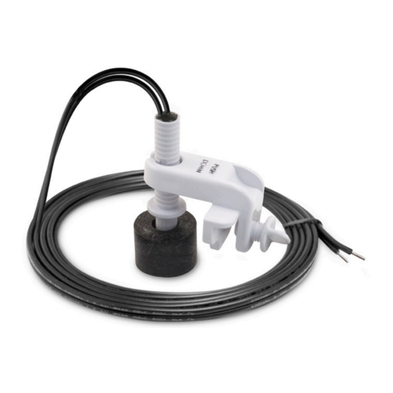
Description
Safe-T-Switch® Model SS3 specially designed mounting bracket mounts firmly over the edge of most drain
pans. The patented magnetic reed switch and slim profile can be installed on primary or auxiliary drain
pans. The SS3 switch is easily removed for cleaning and servicing.
Component List: (See page 3)
(1) Bracket
(2) Stem assembly (includes Float, Tag, and Stem with wire)
(3) Thumb Screw (with 5/16 UNF thread)
(4) Warning Sticker (not shown)
US Patent No. 6,698,215
Specifications
24-Volts A/C, Maximum 1.25 Amp. Carrying Capacity, 6ft., 18 AWG Lead Wires.
Maintenance
Inspect, clean and test this device at least every 30 days and following every cleaning of the drain line. 1. Clear debris or any other obstacles around the
Stem Subassembly. 2. Check for any damage. If damage is observed, replace this product with a new one. 3. Test switch function by following Step 6-7 in the
"AUXILIARY DRAIN PAN INSTALLATION" section below. If this product failed function test, replace it with a new one.
Wiring
Wire Nut
1. Disconnect power to A/C unit at the main panel prior to performing electrical work.
To Switch
From Thermostat
2. If not present, it is recommended that an inline fuse be installed to protect 24-volt circuit and
time delay be configured to avoid rapid cycling of equipment. 3. Locate the 24-volt thermostat
cable entering the air handler unit. 4. Disconnect or cut the red wire and connect to switch lead
using wire nut. Connect other switch lead to air handler terminal. Incorporating switch in red circuit
shuts down entire unit. If placed in the yellow circuit, fan continues to run (to inhibit mold growth
(Fig. 4)
during long absences.) 5. Reconnect power to the A/C unit.
Packaging
Code
Size
Qty. per Case
Lbs. per Case
Cubic Ft per Case
97089
24
5
0.73
Safe-T-Switch SS3
Page 1 of 3
Advertisement

Summary of Contents for RectorSeal SAFE-T-SWITCH SS3
- Page 1 If placed in the yellow circuit, fan continues to run (to inhibit mold growth (Fig. 4) during long absences.) 5. Reconnect power to the A/C unit. Packaging Code Size Qty. per Case Lbs. per Case Cubic Ft per Case 97089 0.73 Safe-T-Switch SS3 Page 1 of 3...
- Page 2 SAFE-T-SWITCH ® For primary and auxiliary drain pans (Fig.1) (Fig.2) (Fig. 3) Push stem to bottom Installation Instructions: Notice: Failure to read and comply with all warnings, cautions and instructions prior to starting installation may cause personal injury and/ or property damage and void the warranty. AUXILIARY DRAIN PAN INSTALLATION (Works with 1-2”...
- Page 3 RECTORSEAL. ANY REPRODUCTION IN OBLIGATION ON THE PART OF RectorSeal, LLC. The sole remedy for breach of the Limited Express Warranty shall be the refund of the purchase price. All other liability is negated and disclaimed, and RectorSeal, ENG APPR.