
Summary of Contents for Peter electronic VersiDrive i Series
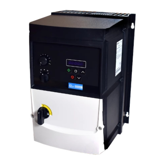
- Page 1 e l e c t r o n i c AC Converter VersiDrive i .../E3S/IP66ODS Quick Start Manual Quality is our drive...
-
Page 2: Prepare The Mounting Location
CHECK: Check the correct drive type, check suitable motor type & info PREPARE: Correct tools, suitable mounting location, weather protection CONNECT: Power & Control connections CHECK: Final check of everything before operation POWER ON COMMISSION the drive parameters OPERATE and check everything is as intended WARNING! The VersiDrive i should ONLY be installed by a qualified electrician. -
Page 3: Mechanical Dimensions
3 MOUNT Mechanical Dimensions Dimensions Weight Frame Size 9, 1 3 6,34 6,37 7,44 148,5 5,85 10, 1 2 7, 1 6 7,87 6,93 Mounting Clearance X Above & Below Y Either Side Drive Size All Frame Sizes 7.87 0.39 Typical drive heat losses are approximately 3% of operating load conditions. -
Page 4: Cable Selection
4 CONNECT Cable Selection For 1 phase supply (Sizes 1-3 only), the mains power cables should be connected to L1/L, L2/N. For 3 phase supplies, the mains power cables should be connected to L1, L2, and L3. Phase sequence is not important. For compliance with CE and C Tick EMC requirements, refer to online documentation. -
Page 5: Control Terminal Wiring
Information for UL Compliance VersiDrive E3S is designed to meet the UL requirements. For an up to date list of UL compliant products, please refer to UL listing NMMS.E226333. In order to ensure full compliance, the following must be fully observed. Input Power Supply Requirements Supply Voltage 200 –... -
Page 6: Motor Thermistor Connection
Switched Units: Default functions of the control switches Switch Position Notes Factory Default Configuration. Run Forward or Reverse with speed controlled from the Local POT. Sets the output frequency Run Reverse STOP Run Forward NOTE Other functions are possible, please refer to the online documentation for additional information. Using the Control Terminals Connection Example Purpose... -
Page 7: Operation
6 POWER ON 7 COMMISSION Operation Managing the Keypad Used to decrease speed in real-time The drive is configured and its operation monitored via the DOWN mode or to decrease parameter values keypad and display. in parameter edit mode. When in keypad mode, used to Start a Used to display real-time information, stopped drive or to reverse the direction START... - Page 8 8 OPERATE Parameters Standard Parameters Par. Description Default Units P-01 Maximum Frequency/Speed Limit P-02 500.0 50.0 (60.0) Hz/RPM P-02 Minimum Frequency/Speed Limit P-01 Hz/RPM P-03 Acceleration Ramp Time 0.00 600.0 P-04 Deceleration Ramp Time 0.00 600.0 P-05 Stopping Mode/Mains Loss Response Setting On Disable On Mains Loss...
- Page 9 Par. Description Default Units P-23 Preset Frequency / Speed 4 -P-01 P-01 P-09 Hz/RPM P-24 2nd Ramp Time (Fast Stop) 0.00 600.0 0.00 P-25 Analog Output Function Select Digital Output Mode. Logic 1 = +24V DC Analog Output Mode 0: Drive Enabled (Running) 8: Output Frequency (Motor Speed) 1: Drive Healthy 9: Output (Motor) Current...
- Page 10 Par. Description Default Units P-46 PI Feedback Source Select 0: Analog Input 2 3: DC Bus Voltage 1: Analog Input 1 4: Analog 1 – Analog 2 2: Motor Current 5: Largest (Analog 1, Analog 2) P-47 Analog Input 2 Signal Format U0-10 : Unidirectional, External 0 –...
-
Page 11: Technical Data
Technical Data Environment Operational ambient temperature range Enclosed Drives: -20 ... 40°C (frost and condensation free) Storage ambient temperature range: -40 … 60°C Maximum altitude: 2000m. Derate above 1000m: 1% / 100m Maximum humidity: 95%, non-condensing Rating Tables Frame Input Fuse/MCB Maximum Cable Output... -
Page 12: Troubleshooting
Troubleshooting Fault Code Messages Fault Code Description Brake channel over current Brake resistor overload Output Over Current Motor Thermal Overload (I2t) Over voltage on DC bus Under voltage on DC bus Heatsink over temperature Under temperature External trip Optibus comms loss DC bus ripple too high Input phase loss trip Output Over Current... - Page 13 +49(0) 9189/4147-0 Fax: +49(0) 9189/4147-47 eMail: mail peter-electronic.com Phone PETER electronic GmbH & Co. KG Bruckäcker 9 D-92348 Berg www.peter-electronic.com...
Need help?
Do you have a question about the VersiDrive i Series and is the answer not in the manual?
Questions and answers