
Summary of Contents for Seeed Mini Soldering iron
- Page 1 Instruction Manual Version 1.1 For your own safety, please read the manual before installing the device (The current version of this instruction manual is APPV2.70)
- Page 3 WARNING:Failure to comply with the WARNING may cause serious injury to the user or others. CAUTION: Failure to comply with the CAUTION may cause damage to the product or other objects. Please pay attention to the Annotations, Operation notes and Additional information.
-
Page 4: Safety Statement
Safety Statement 1.1 General Safety Keep out of reach of children Please choose the certified power source/adapter from your region. (For more detailed information, please refer to 3.0 ) Do not operate under wet condition. Do not operate near flammable or explosive materials. Keeping the surface of the equipment clean and dry. -
Page 5: Liability Statement
350℃. A small chain of smoke may come out due to the high temperature when use for the first time. Do not attempt to repair the Mini Soldering Iron, or the warranty will be invalidated. 1.5 Liability Statement... -
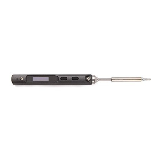
Page 6: Name Of Parts
Overview 2.1 Name of Parts 01. Solder iron tip fixing screw 02. Button A 03. Button B 04. Set screw 05. Power port 06. Micro USB 07. DC5525 12-24V port 08. Solder iron tip connection port 09. solder iron connection side 10. -
Page 7: Operation Specifications
Overview 2.2 Specifications Screen OLED USB port Micro USB Power port DC5525 Length: 96mm, Control knob Diameter: 16.5mm Dimensions Length: 33mm, Heating Part Diameter: 5.5mm 2.3 Operation Specifications Power Temperature range 100℃~400℃(max) Temperature stability ±2% Operation temperature under heat environment Soldering tip resistance value to the ground... - Page 8 Power Adaptor Selection Please ensure the DC5525(12-24V)power adapter is in good condition before connecting it with the Mini soldering iron.Please choose the certificated standard adapters only Time for tip temperature rise from 30℃ to 300℃ under standard operating voltage, power and currents...
-
Page 9: Operation
2.Connect the ground wires with the ground set screw. 3.Connect the DC connector to Mini Soldering Iron, plug the power cord and turn on the device accordingly. Note: Solder tip is connected inappropriate when “sen-err”is displayed on the screen , please reconnect under proper ins- truction. -
Page 10: Basic Control
Operation 4.3 Basic Control 4.3.1 Screen Display P re ss Ver 2 0 1 When the DC12-24V power adapter is plugged into the control part, the boot logo, version number, thermometer and standby image will be displayed in sequence. D FU 1 .0 To enter DFU mode,press Button A after DC12-24V power adapter is plugged into the control part .The OLED screen will display "DFU 1.0"... - Page 11 Operation 4.3 Basic Control 4.3.2 Automatic Calibration Pr es s Press Button B in standby mode to enter the thermometer mode 2 4℃ In thermometer mode press two buttons simultaneously to enter the calibration mode Ca l_X Cal _V Calibration success Calibration failed To exit thermometer mode, long-press any button 2 4℃...
- Page 12 Operation 4.3 Basic Control 4.3.3 Heating up P r e s s 30 0℃ Pressing Button A in standby mode, the temperature of Mini Soldering Iron will rise to the preset temperatures 30 0℃ Ready for soldering In operation mode, press two buttons simultaneously for 3 seconds will return to standby mode...
- Page 13 Operation 4.3 Basic Control 4.3.4 Temperature Adjustment 3 0 0℃ Press button A in Standby 30 0℃ Mode to enter Temperature Adjustment Mode Lower Temperature: Press button A for at least 2 minutes in Temperature Adjustment Mode, and release the button when the 2 46℃...
- Page 14 Operation 4.3 Basic Control 4.3.4 Temperature Adjustment 40 0℃ 10 0℃ Note: Left /Right Arrow ( ) indicates the temperature has reached the maximum or minimum temperature, the s- etting in current state will not be saved when the user turns the power off.
- Page 15 Operation 4.3 Basic Control 4.3.5 Sleep Mode 2 00℃ Rest the Mini Soldiering Iron for 180 seconds ( 3 minutes in de- fault)in Operating Mode will trigger the Sleep Mode and back to the custom sleep mode temperature. 3 00℃ It will go back to operating temperature mode (300℃...
-
Page 16: System Parameters
When operation voltage is Protection lower than default voltage voltage 9-12V MINI SOLDERING IRON will return to standby mode 0 is ℃ Temperature unit selection ℃ Unit setting 1 is ℉ Temperature calibration Temperature... - Page 17 Soldering Iron Tips 5.1 Assemble the Solder Tip 1. Make sure the power is turned off before changing the tip 2. Remove the screw on operation side 3. Remove the tip and replace with another one 4. Fix the tip with the screw Note: An"sen-err"...
- Page 18 Soldering Iron Tips 5.2 Choosing Soldering Iron Tips Note: Selecting a right tip will help you work more efficiently 1 0.0 10.0 15. 0 11.5 TS-D24 TS-K TS-BC2 TS-B2 5.3 Soldering Iron Tip Maintenance (1) Wipe the tip's soldering side with some solder before turning it off.
-
Page 19: Troubleshooting Guide
A4: If the tip is dirty, please refer to Part 5.3 Soldering Iron Tip Maintenance. Q5: OLED displays "Warning!" A1.The Mini Soldering Iron temperature may be higher than the maxi- mum operating temperature The warning sign will disappear after the temperature returns to the... - Page 20 A5. Don’ t use the tip to touch any organic materials such as plastic, silicone oil or other chemicals. Q8: Mini Soldering Iron return to Standby Mode during operation A1:Check whether the voltage is lower than default (10V). If so,...
-
Page 21: Technical Support
7.2 Default Parameter Setting The image "CONFIG" will be shown on the screen after connecting the Mini Soldering Iron to computer with a USB cable. The "CO- NFIG" means you are in Setting Mode, you can set the default p-... -
Page 22: Firmware Update
7.3 Firmware Update 1. For firmware upgrade, please visit: seeed.cc/mini-soldering-iron 2. Hold Button A while connecting Mini Soldering Iron to your computer with a USB cable, screen will display "DFU1.0" after connecting successfully. The virtual drive will be shown in your computer( 8 digit serial number) once the device enters the DFU Mode. -
Page 23: Legal Statements
Legal Statements 8.1 Disposal Do not dispose the product with household waste Handling and Recycling: Please obey the local management regulations and laws. 8.2 8.2 Statement of Fulfilling FCC Standard This device fulfills Part 15 of the FCC regulations Device must fulfill below 2 conditions: (1) Device must not generate interference.
Need help?
Do you have a question about the Mini Soldering iron and is the answer not in the manual?
Questions and answers