Table of Contents
Advertisement
Advertisement
Table of Contents
Troubleshooting

Summary of Contents for Topcon X14
- Page 1 Console Guidance & Auto Steering Operator’s Manual www.topconpositioning.com...
- Page 3 © Copyright Topcon Precision Agriculture April 2016 All contents in this manual are copyrighted by Topcon. All rights reserved. The information contained herein may not be used, accessed, copied, stored, displayed, sold, modified, published or distributed, or otherwise reproduced without express written consent from Topcon.
- Page 5 - No statement contained at the website of TPA WEBSITE AND OTHER STATEMENTS or any other Topcon Group company or in any other advertisements or TPA literature or made by an employee or independent contractor of TPA modifies these Terms and Conditions.
- Page 6 defective item at no charge, and ship it back to you. You must pay the shipping and handling charges in respect of the same. Calibration of components, labor and travel expenses incurred for in-field removal and replacement of components are not covered in this warranty policy. The foregoing warranty shall NOT apply to damage or defects resulting from: (i) disaster, accident or abuse (ii) normal wear and tear...
- Page 7 Other These Terms and Conditions may be amended, modified, superseded or cancelled, at any time by TPA. These Terms and Conditions will be governed by, and construed in accordance with: the laws of South Australia if the product is sold and supplied to you in Australia (in which case the courts of South Australia or the Federal Court of Australia (Adelaide Registry) have exclusive jurisdiction in respect of any claim or dispute) or the laws of the State of California if the product is sold and supplied to you outside of Australia...
- Page 8 You can check if interference is being caused by this equipment by turning the Topcon equipment off to see if the interference stops. If the equipment is causing interference to a radio or other electronic device, try: Turning the radio antenna until the interference stops...
- Page 9 Good safety practices not only protect you, but also the people around you. Study this manual as part of your safety program. This safety information only relates to Topcon equipment and does not replace other usual safe work practices. WARNING: Ensure power is removed from the Topcon equipment prior to maintenance or repair of the vehicle or implements.
- Page 10 However, it is always advisable not to handle damaged elec- tronic equipment. This Topcon product may contain a sealed lithium battery. Always dispose of any electronic equipment thoughtfully and responsibly.
- Page 11 Topcon accepts no responsibility or liability for damages to property, personal injuries, or death resulting from the misuse or abuse of any of its products. Further, Topcon accepts no responsibility for the use of Topcon equipment or the GNSS signal for any purpose other than the intended purpose.
- Page 12 Operation and Risk of Obstacles The following list is not exhaustive or limited. To use the console for assisted steering along a defined wayline, the operator must ensure that it is used: Away from people and obstacles Away from high voltage power lines or other overhead obstructions (identify any clearance problems before activating the console) On private property without public access Within cleared fields...
- Page 13 Be aware of file format compatibility. Discuss compatible formats with the dealer. Topcon Agricultural Products are hardy and designed to work in tough conditions. However, if equipment is unused for a length of time, store away from water and direct heat sources.
-
Page 14: Table Of Contents
Table of contents Chapter 1 – Console Overview 1.1. Introduction 1.2. Starting the console 1.3. Shutting down the console 1.4. Using the console toolbar Chapter 2 – User Interface Description 2.1. Switching between setup and operation screen 2.2. Setup screen controls 2.3. - Page 15 5.2.1. Receiver setup 5.2.2. Correction setup 5.3. Setting up alarms 5.3.1. Alarm window description 5.3.2. Alarms list 5.4. Setting up flag points 5.5. Setting up utilities Chapter 6 – Vehicle Setup 6.1. Selecting a vehicle 6.2. Creating a new vehicle 6.2.1.
- Page 16 9.7.1. Customizing the dashboard 9.8. Storing information about jobs 9.9. Recognizing color and working status 9.10. Understanding default file names Chapter 10 – Steering Calibrations 10.1. Calibrating the compass 10.2. Calibrating the wheel angle sensor 10.3. Calibrating the mounting bias 10.4.
- Page 17 Chapter 14 – Auto Steering 14.1. Auto steer status 14.1.1. Auto steer troubleshooting 14.2. Tuning auto steer 14.3. Engaging auto steer 14.4. Disengaging auto steer Chapter 15 – Nudge Menu 15.1. Using nudge options 15.2. Compensating for GPS drift 15.2.1. Compensating correctly for GPS drift 15.2.2.
-
Page 19: Chapter 1 - Console Overview
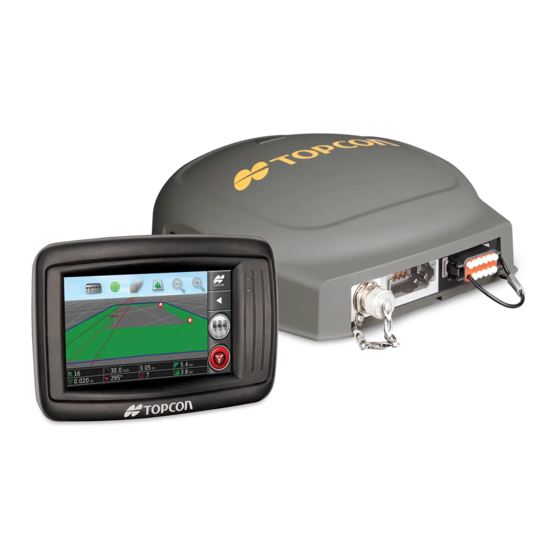
Chapter 1 – Console Overview 1.1. Introduction The X14 is a vehicle-mounted electronic console with LCD display and touchscreen. The console allows operators to work with auto steering, guidance and other control functions from the console. The console is designed to interact with GPS and Electronic Control Units (ECUs), centralizing the ability to communicate, record, store and display data for agricultural uses. -
Page 20: Shutting Down The Console
1.3. Shutting down the console The warning screen displays in the chosen language. 4. Use the scroll bar to display the complete warning screen and if you agree select YES. Note: Selecting Yes confirms your understanding and accepts your responsibility for liabilities described in the warning screen. The console may display the following warning. -
Page 21: Using The Console Toolbar
Chapter 1 – Console Overview 1.4. Using the console toolbar The console toolbar is displayed by swiping upwards from the base of the screen. Power off button The power off button may be used to shut down the console. Help The Help hint feature displays the names of the user interface elements on the screen. - Page 22 1.4. Using the console toolbar Brightness control Brightness control adjusts the brightness of the display. Use plus or minus to adjust display. Day/night mode Day/night mode changes the brightness of the display. Settings are Day, Night and Auto. Auto light mode will set the brightness automatically, depending on light conditions.
-
Page 23: Chapter 2 - User Interface Description
Chapter 2 – User Interface Description 2.1. Switching between setup and operation screen The console has two main screens; the Operation screen and the Setup screen. Use the highlighted buttons to switch between the screens. 2.2. Setup screen controls This section describes the Setup screen controls. The Setup screen has the following types of controls: Menus Menu items are selected from the base of the screen to display the... - Page 24 2.2. Setup screen controls Option lists Selecting menu items will typically display a list of options at the top of the screen. As features are enabled, more options may appear. Selection lists Selection lists are used to choose one or more items from a list. A message is displayed if too many items are selected in a multiple choice list.
- Page 25 Chapter 2 – User Interface Description Keyboard and number-pad Letter and number keypads are used to enter alphanumeric characters or numeric characters. Entries must be confirmed. Wizards Wizards are used to guide the operator through a complex configuration of the system by answering a series of questions. The answers provided determine which questions will follow.
-
Page 26: Operation Screen Controls
2.3. Operation screen controls 2.3. Operation screen controls Lightbar: Used for manual guidance to the set waylines (guidelines). Refer to Setting up the lightbar, page 22. View controls: Allows the user to control what is displayed on the guidance map and how it displays. Refer to Using view controls, page 56. -
Page 27: Implement Color Indicators
Chapter 2 – User Interface Description 2.3.1. Implement color indicators This indicates the position and direction of the vehicle and its implement. The implement color indicates product application status: Red: Section is off. Blue: Section is inhibited (on and not flowing, typically due to low speed or pressure). - Page 28 2.4. Icon descriptions New field, 77 Unload field. 84 Set flag point, 83 Record field boundary, 78 Complete field boundary recording, 78 Boundary recording offset, 78 Clear field boundary, 82 Create boundary from shapefile, 80 Create boundary from coverage, 79 Job menu Job menu, 85 Select job, 86...
- Page 29 Chapter 2 – User Interface Description Guideline menu Guideline menu, 89 Change guidance mode, 89 Select guideline, 92 Create new AB line, 89 Set A point, 90 Open manual AB line entry window, 90 Steering options menu Steering options menu, 95 Auto steer status, 95 Auto steer tuning parameters, 98 Auto steer calibration, 67...
-
Page 30: Navigation Window Icons
2.4. Icon descriptions Nudge guideline to the vehicle's position, 103 Save nudged guideline, 103 GPS drift compensation, 103 2.4.3. Navigation window icons System information, 55 Guidance, 56 GPS information, 60 System diagnostics, 61 Job information, 55 Auto section control, 28 Inventory manager, 107 Switch box, 51 Setup screen, 5... -
Page 31: Other Icons
Chapter 2 – User Interface Description Zoom out/in, 60 2.4.5. Other icons Master switch, 51 Auto steer engage, 95... - Page 32 2.4. Icon descriptions...
-
Page 33: Chapter 3 - Quick Setup Guide
Chapter 3 – Quick Setup Guide This chapter provides a quick overview to installing software onto the console, setting up the basics and operating the console. WARNING: It is not recommended to operate the console for the first time without reading the complete manual to become familiar with all safety and operational issues. - Page 34 3.2. Getting started 4. Once the system receives GPS data for the first time, it will prompt for configuration of the local time. Accept the current time or modify it to your local time. 5. Select Vehicle / New and create a new vehicle profile by selecting the appropriate model from the factory profile.
- Page 35 Chapter 3 – Quick Setup Guide Enable the Auto Section Control feature in System / Implement / AUTO SECTION Features CONTROL (see page 28). 12. To control any of the enabled features from the Operation screen, use the buttons on the Navigation window (see page 55).
- Page 36 3.2. Getting started...
-
Page 37: Chapter 4 - Regional And User Settings
Chapter 4 – Regional and User Settings To access the Setup screen, select the following icons: On the Setup screen, the User menu option provides the following menu items: Region: Selects the language, time/date and units. Lightbar: Sets operation of the LED bar for guidance use. Environment: Sets up console interaction. -
Page 38: Time/Date Setup
4.1. Setting the region To set the language or decimal point format: 1. Select User / Region / Language The following options are available: Language There is a choice of languages available. Use the scroll bar, or slide a finger down the list, to see more languages. -
Page 39: Units Setup
Chapter 4 – Regional and User Settings 4.1.3. Units setup The units options sets the displayed units of measurement (metric or imperial), area and the latitude/longitude format. To set unit information: 1. Select User / Region / Units The following options are available: Units Metric Imperial (US) -
Page 40: Setting Up The Lightbar
4.2. Setting up the lightbar Area units ha (hectare) ac (acre) Default: Selects the default setting appropriate for the selected Units Liquid product volume units Litres Gallons Cubic meters Cubic feet Tonnes Pounds Application rate increment type Fixed rate Percentage of Preset 1 This option changes the behavior when the operator presses the up/down buttons to change the requested product application rate. -
Page 41: Setting Up Environment
Chapter 4 – Regional and User Settings Light bar Enabled or disabled. LED spacing Sets the ground distance from the wayline (guideline) that each LED represents. If the LED spacing is set to 10 cm (0.1 m), the following behavior is observed: The center LED is blue and will be illuminated all the time (unless the cross track error is 100 cm or more). -
Page 42: Setting Up Map Options
AB lines, Pivots, Curves, Optimal lines, Project lines and Field boundaries. System 150 file transfers allow the operator to export files in a format that matches Topcon’s System 110/150 system and import files that were exported from System 110/150. Enabling this option displays the System 150 icon... - Page 43 Chapter 4 – Regional and User Settings Point of focus Vehicle: Places the vehicle at the center of the screen. Implement: Places the implement at the center of the screen. Map panning Allows the screen to move around in a map when the user slides a finger across the screen.
-
Page 44: Setting Access Level
4.5. Setting access level 4.5. Setting access level Setting the access level determines which controls are accessible to the user. To change the access level: 1. Select User / Access Level The Access Level may be set at Easy, Standard or Expert. A password may be set for the Standard and Expert levels to prevent inexperienced users from accessing higher levels. -
Page 45: Chapter 5 - System Setup
Chapter 5 – System Setup To access the Setup screen, select the following icons: This chapter explains how to set up system elements such as GPS connections, alarms and optional features. System menu option provides the following menu items: Features: Enables or disables optional features. GPS: Sets up the functionality of the connected GPS receiver. -
Page 46: Setting Features
5.1. Setting features 5.1. Setting features The Features menu option provides the following menu items: 5.1.1. Guidance setup Sets the guidance system functionality. To set up guidance features: 1. Select System / Features / Guidance Guidance This is a standard feature of the console and cannot be disabled. Auto steer Enables auto steering and can only be used on vehicles fitted with an auto steering system such as the AES-25. -
Page 47: Setting Up Gps
Chapter 5 – System Setup 5.2. Setting up GPS 5.2.1. Receiver setup Sets up GPS receiver capabilities. To set up the GPS receiver: 1. Select System / GPS / Receiver GPS receiver Select the GPS receiver type from the selection list. The console can accept GPS input from a third party GPS receiver provided the receiver can be configured to output the data in the required correct format. -
Page 48: Correction Setup
5.2. Setting up GPS after the vehicle is turned off. The Keep Alive Time determines how long the receiver remains powered. Keep alive time Note: This feature is only available if Use Ignition Line is set to Enabled. (AGI-4 only) Keeps the GPS receiver active after the system has been shut down. - Page 49 Chapter 5 – System Setup Correction sources Correction Description Source Autonomous Let the receiver find any free available satellites. Will not use any correction. Precision: 2 - 5 m. Automatic Let the receiver select the best available correction source. WAAS Use Wide Area Augmentation System.
- Page 50 Description GLONASS Allows the GPS receiver to use the Russian satellite navigation system GLONASS, in addition to GPS. TRUPASS Topcon’s GPS drift compensation algorithm, used to provide better pass to pass performance. Available with the following correction sources: Autonomous, WAAS, EGNOS, MSAS, OmniSTAR VBS.
- Page 51 Chapter 5 – System Setup Option Description Baud Rate The data transmission rate for modems. Refer to documentation supplied with modem. Some network providers require a GGA (position) to be Output sent to them to allow them to identify the location of the rover (tractor).
-
Page 52: Setting Up Alarms
5.3. Setting up alarms Note: If RTK is selected and an AGI-3 or AGI-4 is connected, the base station settings can be automatically synced with the entered receiver settings. Select System / GPS / Base Station Sync and follow the instructions displayed on the wizard. VTG legacy mode: Supports VTG data output for NMEA standards below V4.00. -
Page 53: Alarms List
Chapter 5 – System Setup The alarm window may be dragged down to display additional details about the alarm if Drag down for details is displayed at the top of the alarm window. The speaker icon may be used to mute the alarm. The spanner icon displays the appropriate alarm setup page to configure that alarm (or disable it if it’s not relevant to your current setup). - Page 54 5.3. Setting up alarms Alarm Description GPS drift Triggered on startup as an informational reminder that correction the GPS drift correct has been applied. Since GPS drift varies with time this is a reminder that GPS drift compensation may need to be recalculated. GPS lost Triggered when the GPS signal is lost but the receiver is still connected.
- Page 55 Chapter 5 – System Setup Alarm Description Triggered when the length of the recorded line exceeds guideline the maximum number of points (typically several length kilometres, but will vary based on how complex the exceeded curve is). No comms Triggered if the console is unable to communicate with the implement ECU.
-
Page 56: Setting Up Flag Points
5.4. Setting up flag points Alarm Description Reverse Informational alarm triggered when the operator’s seat is station rotated by 180 degrees (only applicable for tractors with dual driving stations). Steering Triggered when the steering has been disengaged. This disengage may be due to losing satellites, losing the guideline or (visual) manually turning the steering wheel. -
Page 57: Setting Up Utilities
Chapter 5 – System Setup 3. Select the new symbol or select FLAG POINT NAME and type in the new name for the flag, then confirm. Note that flags can be changed but new preset flags cannot be created. 5.5. Setting up utilities 1. - Page 58 5.5. Setting up utilities...
-
Page 59: Chapter 6 - Vehicle Setup
Chapter 6 – Vehicle Setup To access the Setup screen, select the following icons: This chapter explains how to set up and access profile information about the vehicle on which the console is mounted. If the console is to be used on more than one vehicle then more than one vehicle profile must be set. -
Page 60: Selecting A Vehicle
6.1. Selecting a vehicle Antenna: Sets whether the GPS receiver has an internal or external antenna. 6.1. Selecting a vehicle Selects a vehicle from a previously defined list of vehicle profiles. This is blank when the console is first used. To select a vehicle: 1. -
Page 61: Customizing A Vehicle
Chapter 6 – Vehicle Setup are appropriate, select Other and go to Customizing a vehicle, page Note: Select to go up one level to the parent folder. 3. Select the vehicle model and confirm. 4. To change the name, select VEHICLE NAME, enter the name and confirm. - Page 62 6.3. Setting the vehicle geometry To set the vehicle geometry: 1. Select Vehicle / Geometry . Alternatively, the Vehicle Geometry screen displays automatically when a vehicle is created or selected. 2. Select a vehicle dimension. Dimensions requested vary according to the type of vehicle selected.
-
Page 63: Setting Up The Steering Controller
Chapter 6 – Vehicle Setup 6.4. Setting up the steering controller Controls how the vehicle will respond to guidance. Refer to Auto Steering, page 95. This option is only visible if AUTO STEER is enabled on System / Features / Guidance. To set up the steering controller: 1. -
Page 64: Selecting The Vehicle Antenna
6.5. Selecting the vehicle antenna 6.5. Selecting the vehicle antenna Sets whether the GPS receiver has an internal (built into the receiver) or external antenna. Internal antenna is set as default. To set the antenna type: 1. Select Vehicle / Antenna If External is selected, the measurements for the location of this antenna must be entered: Forward offset to AGI-4 (or AGI-3) -
Page 65: Chapter 7 - Implement Setup
Chapter 7 – Implement Setup To access the Setup screen, select the following icons: This chapter explains how to set up and access profile information about the implement being used. If the console is to be used with more than one implement, then more than one implement profile must be set up. -
Page 66: Selecting An Implement
7.1. Selecting an implement New: Create a new implement profile. Speed: Refer to Setting up GPS speed emulation, page 52. 7.1. Selecting an implement Selects an implement from a previously defined list of implement profiles. This is blank when the console is first used. To select an existing implement: 1. -
Page 67: Setting The Implement Geometry
Chapter 7 – Implement Setup Note: It is highly recommended that items are named in a thoughtful and structured way to allow easy use in future seasons. 3. To change the default name, select IMPLEMENT NAME and enter the new name, then confirm. 7.3. -
Page 68: Setting Up Section Control
7.4. Setting up section control Inline Offset: Measures the off-center offset of the implement relative to the hitch point. Enter a positive number if the implement is shifted to the right and a negative number if it is shifted to the left. Trailer Offset: Measures the distance between the trailer hitch point and the trailer wheels. -
Page 69: Setting Up The Section Switch
Chapter 7 – Implement Setup 1. Select Implement / Section Control / Timing 2. Select ON TIME to set how many seconds delay there is between switching a section on and the application of product, then confirm. 3. Repeat for OFF TIME and confirm. This will set how many seconds delay there is between switching a section off and stopping product flow. -
Page 70: Setting Up Gps Speed Emulation
7.6. Setting up GPS speed emulation Refer to the manual for the implement controller for information on setting up the switches for the implement. External console input Enables the master switch to be operated via an external switch (a physical switch box / master switch connected to the console). Note: If an external switch is connected, this is usually done by the dealer during installation. -
Page 71: Chapter 8 - Product Setup
Chapter 8 – Product Setup 8.1. Setting up the product database Product definitions can be saved in one common area. This allows common products to be used across a range of rate controllers without having to enter each product name and rate repeatedly. Pre-set rates, increments and product densities can be set up and saved to be recalled in the appropriate rate controller. - Page 72 8.1. Setting up the product database...
-
Page 73: Chapter 9 - Operation Basics
Chapter 9 – Operation Basics 9.1. Using the window toolbar The Window Toolbar is used to access the tools used to control guidance. Selecting a tool displays the sub-menu options. 9.2. Using the navigation window The Navigation Window is used to display information screens, the guidance screen and the inventory manager. -
Page 74: Viewing Guidance
9.3. Viewing guidance System diagnostics. Displays memory usage, console diagnostics and trouble codes. Refer to Viewing system diagnostics, page 61. Job information. Displays job statistics, duration, settings, notes and guidance settings. Refer to Viewing job information, page 61. Auto section control configuration. Refer to Implement setup, page 28 for setup. - Page 75 Chapter 9 – Operation Basics Select mode There is a new touchscreen mode available. To use this mode, press and hold on the screen for half a second then drag your finger over the required object to select it. Once the mode is engaged, the select mode icon becomes visible and the object is highlighted.
- Page 76 9.3. Viewing guidance Coverage map The coverage map selector enables one type of coverage map to be selected. This is done by pressing the center button and selecting from a list or by pressing the left/right arrows to scroll through the list with a live preview of that layer in the map in the background.
- Page 77 Chapter 9 – Operation Basics 1. Click on the legend to display the legend color and range map. 2. Select Edit to change the colors and ranges used. Toggle map view mode 1. Select to toggle views of the map (North Up, Overhead or Perspective).
-
Page 78: Viewing Gps Information
9.4. Viewing GPS information Map zoom Select to zoom in or out if needed. Press and hold to zoom quickly. 9.4. Viewing GPS information To view and monitor GPS information: 1. Select GPS Information from the Navigation window . Positioning information displays. Latitude and Longitude show the positioning of the vehicle. -
Page 79: Viewing System Diagnostics
Chapter 9 – Operation Basics HDOP < 1.0 Good accuracy HDOP between 1.0 and 4.0 Average accuracy HDOP > 4 Poor accuracy GPS invalid 0 No signal The HRMS (Horizontal Root Means Squared) calculates an average horizontal position from the source information from the satellites. 9.5. -
Page 80: Monitoring On The Dashboard
9.7. Monitoring on the dashboard Guidance Settings Job Notes - Select anywhere in the Job Notes screen to bring up a keyboard. If an implement with more than one boom is selected, an icon is displayed to select the boom about which to view information. 9.7. - Page 81 Chapter 9 – Operation Basics Satellite icon A green satellite icon shows that the GPS and correction source are converged and is based on HDOP. Other colors indicate that information is not available: Grey: No correction source, no signal Red: Poor accuracy Yellow: Average accuracy Green: Good accuracy Note: If AUTOMATIC was chosen during GPS setup, the colors may...
-
Page 82: Storing Information About Jobs
9.8. Storing information about jobs Guidance information The guidance information panels may be configured to display one or two of six possible options: cross track error, speed, heading, swath, area worked or area remaining. Cross track error: Displays the distance of the vehicle from the nearest wayline. -
Page 83: Understanding Default File Names
Chapter 9 – Operation Basics 9.10. Understanding default file names When new vehicles, implements, guidelines or jobs are created, the system displays a default name that can be changed by the operator. Vehicles and implements are named as follows: <Vehicle Type/Implement Type>_XX The _XX is appended if an implement of that name already exists (for example: Pivoted and Pivoted_01). - Page 84 9.10. Understanding default file names...
-
Page 85: Chapter 10 - Steering Calibrations
Chapter 10 – Steering Calibrations The console uses the satellite data it receives, through the receiver attached to the top of the vehicle, to identify the precise coordinates of the vehicle. Using this and other data, the system is able to estimate the vehicle’s position and control the vehicle’s steering system. -
Page 86: Calibrating The Wheel Angle Sensor
10.2. Calibrating the wheel angle sensor The Steering Calibration screen displays. 2. Select COMPASS. If the component reports as calibrated, still complete the calibration procedure if the receiver has not been calibrated on this vehicle. 3. Read the screen and find an appropriate flat place away from high voltage and large metal objects. - Page 87 Chapter 10 – Steering Calibrations WARNING: Ensure there is sufficient space for the vehicle to complete the full maneuver before selecting Next. The calibration will take up to 60 seconds in each of these locked modes. WARNING: Some vehicle models may automatically move the wheels to the required position.
-
Page 88: Calibrating The Mounting Bias
10.3. Calibrating the mounting bias 4. Turn the steering wheel full lock to the left and select next 5. Turn the steering wheel full lock to the right and select next. 6. Ensure the vehicle is still moving at 2 kph (1.2 mph). Turn the steering wheel as close to the center position as possible. - Page 89 Chapter 10 – Steering Calibrations Note: Mounting bias calibration should be performed if any of the above change or at a minimum once every 6-12 months. It is advisable to still perform a mounting bias calibration when using Autonomous as the Correction Source, even though the screen reports that it is not required.
- Page 90 10.3. Calibrating the mounting bias the end of the pass and repeats the procedure. It is important that the vehicle meets the ‘A’ and ‘B’ waypoints within approximately 30 cm, to initiate the next step in the calibration procedure. 3. Reposition the vehicle in an open area. When ready to start the procedure, select to mark the ‘A’...
- Page 91 Chapter 10 – Steering Calibrations This indicates the system has enough data for the first stage of the calibration and the mounting bias calibration will be paused at this point. 11. Proceed to cross the ‘A’ waypoint. 12. When the ‘A’ waypoint has been crossed, turn the vehicle around. 13.
-
Page 92: Dealing With Calibration Errors/Alarms
10.4. Dealing with calibration errors/alarms 20. Confirm to return. Steering Status box indicators will now all be green. 10.4. Dealing with calibration errors/alarms The following errors/alarms can occur during calibrations. Perform the recommended procedures below to fix the errors. View Error Steering controller not initialized The steering subsystem is not turned... - Page 93 Chapter 10 – Steering Calibrations View Error Parameters Mismatch Vehicle geometry parameters do not match the geometry configuration in the steering system. Re-select the vehicle on the Setup screen or ensure the vehicle geometry in the vehicle geometry screen is correct. Receiver Disconnected The AGI receiver has shutdown, lost power or the receiver –...
- Page 94 10.4. Dealing with calibration errors/alarms View Error Wheel Angle Sensor Calibration Failed Repeat procedure and ensure the steering axle moves through the complete range. Confirm wheel angle sensor position information moves when steering axle is turned. Confirm wheel angle sensor harnesses and connections.
-
Page 95: Chapter 11 - Field Menu
Chapter 11 – Field Menu This chapter details how to set client, farm, field, boundaries and flag points. These are the first steps when beginning a job. The console will store the field information so that, once set up, the field details can be recalled for other jobs in the same field. -
Page 96: Setting A New Boundary
11.3. Setting a new boundary 1. Select / Field Menu / Select Field 2. Select the required client, farm and field, then confirm. 3. To import field information from a USB, select USB 4. To select the nearest field, select Nearest Field The current GPS position is used. -
Page 97: Creating A Boundary From Coverage
Chapter 11 – Field Menu the implement. Additional Offset: Enter a positive value to extend the offset beyond the edge of the implement. A negative value positions the offset within the implement extents. Recording Position: Select to record the boundary from the front or rear of the implement, or from the position of the vehicle. -
Page 98: Creating A Boundary From A Shapefile
11.3. Setting a new boundary panel. Smoothing: The minimum gap size that will be automatically filled when creating a boundary from coverage. Minimum coverage area: Any coverage smaller than the area specified here will not automatically create a boundary. Distance from coverage: Expands the created boundary the specified distance from the coverage. - Page 99 Chapter 11 – Field Menu 6. Select a folder to open it. Find the required file and select it. It will display as white and next is now enabled. 7. Confirm to import the shapefile boundary.
-
Page 100: Editing A Boundary
11.3. Setting a new boundary 11.3.3. Editing a boundary Once a boundary has been created, it can be edited. 1. Press and hold to select the boundary on the touchscreen. The boundary is highlighted. Release to display the Edit Boundary screen. -
Page 101: Setting Flag Points
Chapter 11 – Field Menu 2. Select / Field Menu / Select Field to choose the client, farm and field names. The boundary will appear on the screen. 3. To remove the boundary, select Clear Boundary . A message will ask for confirmation. Note: Erasing boundaries is a permanent action. -
Page 102: Unloading A Field
11.5. Unloading a field 2. Select: Change to choose a different flag point. Rename to change the name showing on the flag point. Delete to remove the selected flag point or Clear All to clear all flag points from the field. GPS Drift Correction to move the vehicle to the flag point location to compensate for GPS drift. -
Page 103: Chapter 12 - Job Menu
Chapter 12 – Job Menu The Job Menu selects or sets up specific job information associated with the chosen field. Using this menu, the job information is stored and activity can be recorded and reported. 12.1. Creating a new job 1. -
Page 104: Selecting An Existing Job
12.2. Selecting an existing job 2. Select the region types to be included and excluded for the current job. Note: Areas that will be treated are shown as a lighter grey area on the map (if auto section control is enabled and the Boundary Limit is not set to Unlimited). -
Page 105: Exporting A Job Report
Chapter 12 – Job Menu 3. Use the scroll bar or use the hide arrow to see crop and product options. 4. Select CROP NAME, enter the name and confirm. 5. Select categories as needed, enter the information and confirm. The Product section of this screen is intended to record the specific product mix that is being used for this job. -
Page 106: Clearing A Job
12.5. Clearing a job Before removing the USB, always disconnect first by touching the USB Eject icon (refer to Using the console toolbar, page 3). A message will display that it is safe to remove the USB. If this is not done, the report may be missing or corrupt. -
Page 107: Chapter 13 - Guideline Menu
Chapter 13 – Guideline Menu Guidelines are used to indicate the path that the vehicle should travel for optimum coverage. The system will use the implement width to set evenly spaced lines across the field. If some guideline types are not required, they can be disabled. Refer to Guidance setup, page 28. -
Page 108: Setting Ab Lines Manually
13.1. Using straight lines guidelines 3. To set the AB line, select Create New AB line 4. To change the default name, select GUIDELINE NAME. 5. Enter a name and confirm. Confirm the new guideline. 6. Drive to the start of the swath. Select Set A Point 7. -
Page 109: Using Identical Curve Guidelines
Chapter 13 – Guideline Menu 13.2. Using identical curve guidelines Some fields are not rectangular and have a curved or shaped boundary. For these, identical curves may be the best option for guidelines. This can be useful for steering the boundary of a field and using this guideline for future operations. -
Page 110: Using Guidelock Guidance Mode
13.4. Using guidelock guidance mode 2. Select / Guidelines Menu / Change Guidance Mode, if necessary, to choose Center Pivot Lines 3. Select Create New Center Pivot 4. Select GUIDELINE NAME. 5. Enter a name and confirm. Confirm the new guideline. 6. - Page 111 Chapter 13 – Guideline Menu 1. From the Guidelines Menu , select the required guideline mode, then select Select Guideline 2. Select client, select farm and select field. Existing guideline sets will display. 3. Choose the guideline set required and confirm.
- Page 112 13.5. Selecting an existing guideline...
-
Page 113: Chapter 14 - Auto Steering
Chapter 14 – Auto Steering The Steering Options Menu allows the operator to set options for the auto steering. To use this feature, it must be enabled. If it has not been enabled, refer to Guidance setup, page 28 to enable auto steering. -
Page 114: Auto Steer Troubleshooting
14.1. Auto steer status 14.1.1. Auto steer troubleshooting Error Display Actions Page Auto Steering Engage is showing red. Auto steering does not engage. Select Auto Steering Engage to bring up the Steering Status panel. Red on the panel indicates that the item is not working correctly. - Page 115 Chapter 14 – Auto Steering Error Display Actions Page Steering controller Confirm controller is connected and displays with red turned on. Confirm that the correct steering controller has been selected during setup. If using AES-25, power cycle the AES- 25, then turn wheel a ¼ turn to enable steering.
-
Page 116: Tuning Auto Steer
14.2. Tuning auto steer Error Display Actions Page Prohibited Steering cannot be engaged while operation certain actions are being performed. For example; steering calibration, changing GPS settings, exporting a job. Operator presence The steering system will disengage if the driver leaves the control seat. Steering wheel Let go of the steering wheel and try again. - Page 117 Chapter 14 – Auto Steering Online Aggressiveness sets how aggressively the steering will try to follow the guideline. Approach Aggressiveness sets how aggressively the steering will approach the line. If too high, the vehicle may turn sharply. Maximum Steering Angle limits the angle of turn to stay within the limits of the vehicle’s safe capability.
-
Page 118: Engaging Auto Steer
14.3. Engaging auto steer AES-25 Note that if AES-25 is selected in the setup screen (Vehicle / Steering / CONTROLLER), three new options are added to this screen: AES-25 Sensitivity Adjustment: Adjusts the responsiveness of the steering when following guidelines. AES-25 Deadband Adjustment: Adjusts the amount of movement the AES-25 needs to make before the wheels respond. -
Page 119: Disengaging Auto Steer
Chapter 14 – Auto Steering Auto Steer is ready to use. Select Auto Steer Engage to begin. Auto Steer is engaged and active. Select Auto Steer Engage to change back to manual control. Note that the button may briefly flash blue before turning green. Auto steer cannot engage. - Page 120 14.4. Disengaging auto steer Turn the steering wheel a few degrees OR Select the Auto Steer Engage button on the console to disengage If using an external steering switch, disengage using the switch. WARNING: Before leaving the vehicle, disengage auto steer, turn off the steering switch and remove the key.
-
Page 121: Chapter 15 - Nudge Menu
Chapter 15 – Nudge Menu The Nudge menu allows for minor adjustments to the guidelines that have been set. This is useful for slightly realigning the guidelines to changing conditions or when returning to a field the next season. Guidelines can be nudged in a number of ways. Nudge works with AB lines, center pivot guidelines and identical curves. -
Page 122: Compensating Correctly For Gps Drift
15.2. Compensating for GPS drift change in the reported vehicle position with respect to fixed objects such as the field boundary or guidelines. This is largely due to changes in the satellite constellation patterns. Other factors such as having no clear access to the sky (operating near trees or other obstacles) and satellite data errors may also result in a drift. -
Page 123: High Accuracy Correction Sources
Chapter 15 – Nudge Menu 1. Drive the vehicle to an identifiable location within the field (for example, next to a gate, the corner of the field or in the previous year’s wheel tracks). 2. Use the GPS Drift Options window to position the vehicle on the map relative to these fixed landmarks. - Page 124 15.2. Compensating for GPS drift...
-
Page 125: Chapter 16 - Inventory Manager
Chapter 16 – Inventory Manager The Inventory Manager allows the operator to search for and view details of information items on the system, and make changes to that information. Items can be deleted, renamed, transferred to USB or imported from USB. 1. -
Page 126: Searching Categories
16.1. Searching categories Delete selected items. Export selected items. 16.1. Searching categories The search function allows categories to be searched using a keyword. It is possible to search in multiple fields, farms or clients at once. Navigate up the file hierarchy before pressing the search button to search through all items below that level. - Page 127 Chapter 16 – Inventory Manager Jobs can be searched by keyword, a date range, whether the item is empty or not (useful for deleting empty jobs) and the implement used. The date is shown as DD/MM/YYYY or MM/DD/YYYY depending on the date format selected (see Time/date setup, page 20).
- Page 128 16.2. Searching exporting jobs...
-
Page 129: Chapter 17 - Troubleshooting Guide
Chapter 17 – Troubleshooting Guide 17.1. Common error messages For many errors an error code, or Trouble Code, will display. It is also possible to view errors via the Steering Status screen (see page 95), or the Diagnostics screen, Trouble Codes tab (see page 61). The errors listed below are fairly common and may be corrected by the user. - Page 130 17.1. Common error messages Code Fault Action Page U1065 Wheel angle sensor A change of tires is a calibration required. common cause but is not the only possible cause. Confirm vehicle measurements and then recalibrate. U1066 Compass calibration Calibrate compass. required.
- Page 131 Chapter 17 – Troubleshooting Guide Code Fault Action Page U1074 AES-25 steering Manually turn steering controller not wheel by one quarter initialized. revolution. U1075- CAN receive or Confirm connections. U1078 transmit errors. Power cycle the junction box. Contact dealer if the problem persists.
- Page 132 17.1. Common error messages Code Fault Action Page U5001 Steering subsystem Confirm that steering not detected. subsystem is turned on. Confirm that ‘road lock switch’, which prevents engaging while on public roads, is off. Return to main setup menu to confirm correct steering system in setup.
- Page 133 Chapter 17 – Troubleshooting Guide Code Fault Action Page U6905 Unknown machine Return to main setup type. menu, and revise vehicle setup. U8505 Factory calibration Calibrate compass, wheel 67 - 70 not present. angle sensor and mounting bias. No 12V power Confirm connections.
- Page 134 17.1. Common error messages...
-
Page 135: Chapter 18 - Appendices
Chapter 18 – Appendices 18.1. Appendix A – Glossary Base A GNSS receiver that supplies differential corrections Station to receivers equipped with GNSS. Also called a base or a reference station. Baud Rate This is the speed of data transfer, measured in bits per second. - Page 136 18.1. Appendix A – Glossary Fallback Satellites and correction sources require specific position accuracy when computing the position of the vehicle. If the system is not receiving enough data to compute the vehicle’s position with the required accuracy, auto steering will not be enabled. The fallback feature allows the system to bypass the position accuracy requirement so that auto steering can be engaged.
- Page 137 Chapter 18 – Appendices Latitude The distance of a position north or south of the equator measured in degrees. One minute latitude is equal to one nautical mile (1852 m). The equator has a latitude of zero. Longitude The distance of a position east or west from the prime meridian measured in degrees.
- Page 138 18.1. Appendix A – Glossary Association of base stations that transmit their position Network data to a server via the internet (NTRIP). The vehicles in the RTK network (rovers) also transmit their position to the server via mobile radio. The server uses the position data from the base stations and vehicles to calculate the correction data for each vehicle and transmits it to the vehicle via mobile radio.
-
Page 139: Appendix B - Technical Information
Chapter 18 – Appendices 18.2. Appendix B – Technical Information Console specifications Operating voltage: 9 to 36 V DC Operating temperature: -30 to +65 Storage temperature: -40 to +85 Power consumption: current at 13.5 V DC: 0.5 A current at 27 V DC: 0.25 A... - Page 140 18.2. Appendix B – Technical Information...
-
Page 141: Chapter 19 - Index
Chapter 19 – Index AB lines 89 flag points alarms 34 customize 83 auto section control 28 remove 83 auto steer 28 set 83 disengaging 101 setup 38 engaging 100 glossary 117 status 95 troubleshooting 96 accuracy 60 tuning 98 correction 30 auto steering 95 details 60... - Page 142 lightbar 22 longitude 21 map layers 57 map zoom 60 master switch 51 mounting bias calibration 70 navigation window 55 NTRIP 33 nudge offset 103 to vehicle 103 OAF file 30 product database 53 section control 50 section switch 51 timing 50 software upgrade 15, 39 steering calibration 67...
- Page 144 Avenida de la Industria 35 Tres Cantos 28760, Spain Phone: +34-91-804-92-31 Fax: +34-91-803-14-15 Topcon Corporation 75-1 Hasunuma-cho, Itabashi-ku Tokyo 174-8580 Japan Phone: +81-3-5994-0671 Fax: +81-3-5994-0672 © 2016 Topcon Precision Agriculture All rights reserved Specifications subject to change without notice AGA5495...
Need help?
Do you have a question about the X14 and is the answer not in the manual?
Questions and answers