Table of Contents

Summary of Contents for Beluk EMM5
- Page 1 Reference Manual Rev. 11 Power Analyzer EMM5 2018-07 Reference Manual POWER-ANALYZER EMM5 Beluk GmbH Tel.: +49/(0)8861/2332-0 Taubenstrasse 1 Fax: +49/(0)8861/2332-22 86956 Schongau E-Mail: blr@beluk.de Germany Web: http://www.beluk.de...
- Page 2 Reference Manual Rev. 11 Power Analyzer EMM5 2018-07 Document history Date Name Revision Change 05.04.04 initial document release features of new software revision (V1.02) added 07.06.04 to manual, general updates 14.12.04 features of new software (V1.05) 18.03.05 features of new software (V1.06) features of new software (V1.07)
-
Page 3: Table Of Contents
Reference Manual Rev. 11 Power Analyzer EMM5 2018-07 Contents OVERVIEW ................................4 MEASUREMENT SYSTEM ............................. 5 Data collection ..............................5 Measurement values ............................6 ALARM SYSTEM ..............................7 Alarm display ..............................8 USER INTERFACE ..............................9 Main menu ..............................9 Measurement ..............................10... -
Page 4: Overview
2018-07 1 Overview The EMM5 power analyzer has been designed to provide a great variety of information from the power distribution system it supervises. It contains a powerful measurement system which is able to provide high-precision values from 3- phase systems. -
Page 5: Measurement System
EMM5. This supplies the software with enough information to calculate all the values. The sampling of the input signal needs to be synchronized to the input signal, so the EMM5 needs at least one input signal for the voltage L1-N to be able to do calculations. If this voltage is too small or even disconnected, the device will not be able to do any measurements. -
Page 6: Measurement Values
Reference Manual Rev. 11 Power Analyzer EMM5 2018-07 Measurement values The measurement system uses the information from the data collection system to calculate the values of the power grid. Values, which are directly calculated from the raw input data: ... -
Page 7: Alarm System
The signs are automatically interpreted as inductive or capacitive. The user of the EMM5 will always see a "ind" or "cap" mark with reactive values, so he never needs to worry about interpretation of signs with any reactive value. -
Page 8: Alarm Display
Reference Manual Rev. 11 Power Analyzer EMM5 2018-07 This alarm system reaches its maximum flexibility by these features: Multi-source alarm One single output relay, if available for alarms, can be triggered by any of the 32 alarms. More than one alarm can be used to trigger the same relay. -
Page 9: User Interface
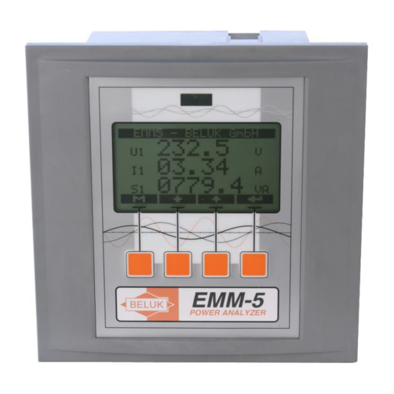
4 User Interface The EMM5 user interface uses a combination of a graphical LC display with automatic backlight and four multi-function softkeys. The action, a key performs, depends on the actual context and is given by small icons at the bottom of the display. -
Page 10: Measurement
The navigation through the values is quite easy: You can use the "" and "" keys to select the different pages. Press one of the keys repeatedly to see all the values. If the last page is reached, the EMM5 continues with the first page. -
Page 11: Work
Reference Manual Rev. 11 Power Analyzer EMM5 2018-07 odd harmonics on the left side, even harmonics on the right. The numbers before the harmonic value gives the order of the harmonic (01 = fundamental wave). KEYS: Left key (“M”) switches back to main menu ... -
Page 12: Setup
Setup The “SETUP”-menu contains all settings, which can be performed by the user of the EMM5 to adjust it to certain ambient circumstances. Because there are many possible settings, the “setup”-menu is divided into more submenus to provide easy and logical access to all the set-up possibilities. - Page 13 PT RATIO: This sets up the device to work with a voltage measurement transformer. Enter the transformer ratio. The range is 1-4000. If no transformer is used and the EMM5 is directly connected for voltage measurement, enter factor 1.
- Page 14 2018-07 4.6.3 Alarm This submenu contains all settings, which have to be performed in order to use the EMM5 alarm system. The menu contains a set of different settings, between which the user can select with the “” key. ...
- Page 15 Reference Manual Rev. 11 Power Analyzer EMM5 2018-07 Example of use: This sample alarm setting is used to signal the total energy flow direction to an external device by use of two alarm relays. The following specifications have to be met: ...
- Page 16 Reference Manual Rev. 11 Power Analyzer EMM5 2018-07 4.6.5 Impulse (optional) This menu item can only be seen, if the device is equipped with the optional impulse outputs. These 4 transistor outputs (galvanic isolation by optocouplers) are dedicated to the counters. With these outputs e. g. external counters can be driven.
-
Page 17: Device Info
In this submenu all counters can be set to 0. All available counters are set to 0 simultaneously! 4.6.11 Clear Datalogger In this menu, all values stored in the memory will erased. Device info This menu simply shows some information about the EMM5 device: SW: software version e. g. 1.09.2... - Page 18 Reference Manual Rev. 11 Power Analyzer EMM5 2018-07 HW: hardware revision number e. g. 0511R06 SN: serial number of the device e. g. 7777777 FLAGS: options of the device e. g. –MB for option Modbus Event History If the EMM54 is equipped with a data logger (option –DM), it’s possible to store occurring alarms with time stamp.
-
Page 19: Connection Diagrams
2018-07 5 Connection diagrams The EMM5 can be used in power systems with or without the neutral conductor. Below measurements in systems with L1/L2/L3 and N (PEN) are called four-wire measurement. Measurements in systems without N are called three-wire measurement. -
Page 20: 3-Phase Measurement Without Neutral Conductor With Three Current- And Three Voltage Transformers (Three-Wire Measurement)
Reference Manual Rev. 11 Power Analyzer EMM5 2018-07 3-phase measurement without neutral conductor with three current- and three voltage transformers (three-wire measurement) 3-phase measurement with two current- and three voltage transformers (three-wire measurement) -
Page 21: 3-Phase Measurement With Two Current Transformers (Three-Wire Measurement)
Reference Manual Rev. 11 Power Analyzer EMM5 2018-07 3-phase measurement with two current transformers (three-wire measurement) 3-phase measurement with three current transformers and measured neutral conductor current (four-wire measurement) -
Page 22: Technical Data
Reference Manual Rev. 11 Power Analyzer EMM5 2018-07 6 Technical data Auxiliary voltage 207 - 253V, 45 - 65Hz, max. fuse 6A Voltage measuring L-N 50V .. 289V, L-L 90V .. 500V, 45 – 65Hz, PT-ratio 1 - 4000 Current measuring 0 –...
Need help?
Do you have a question about the EMM5 and is the answer not in the manual?
Questions and answers