
Related Manuals for Fervi 0664

Summary of Contents for Fervi 0664
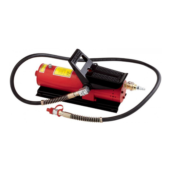
- Page 1 OPERATION AND MAINTENANCE MANUAL Hydraulic pump with pneumatic pedal control Art. 0664 ORIGINAL INSTRUCTIONS...
- Page 2 Manual on the date of issuance and listed herein; On the other hand, the machine may also be subject to important technical changes in the future, without the manual being updated. Therefore, contact FERVI for information about modifications that may have been implemented. REV. 1...
-
Page 3: Table Of Contents
MACHINES AND ACCESSORIES INDEX GENERAL INFORMATION................4 GENERAL SAFETY WARNINGS ..............5 Technical support.......................5 Other provisions ......................5 INTENDED USE AND DESCRIPTION OF THE PUMP........6 Identification Plate and Pictograms ................7 Safety devices......................7 TECHNICAL SPECIFICATIONS ..............8 IMPROPER USE AND HAZARDS ..............8 TRANSPORTING, LIFTING AND MOVING ........... -
Page 4: General Information
The purpose of this manual is to provide the knowledge necessary for the use and maintenance of the Air powered Hydraulic Pump Art. 0664 and create a sense of responsibility and an understanding of the capabilities and limitations of the means entrusted to the operator. -
Page 5: General Safety Warnings
MACHINES AND ACCESSORIES 2 GENERAL SAFETY WARNINGS Even if you are already familiar with the Hydraulic Pump, you must read this manual carefully to acquire full knowledge of the machine and general precautions to be observed during operation. Risks associated with using the machine ... -
Page 6: Intended Use And Description Of The Pump
ACCESSORIES 3 INTENDED USE AND DESCRIPTION OF THE PUMP The Hydraulic Pump Art. 0664 is designed to provide pressure to cylinders or single-acting hydraulic tools. The pump must be used on surfaces that are supportive, flat, smooth, and adequately strong and hard. -
Page 7: Identification Plate And Pictograms
MACHINES AND ACCESSORIES 3.1 Identification Plate and Pictograms The identification plate is attached to the hydraulic cylinder. (Figure 2). Figure 2 - Identification Plates 3.2 Safety devices The flexible tube that carries the high-pressure hydraulic oil, is connected by an external hose and protected by a metal connector, which is adapted to prevent excessive bending at the connection points. -
Page 8: Technical Specifications
MACHINES AND ACCESSORIES 4 TECHNICAL SPECIFICATIONS Unit of Description Art. 0664 measurement Nominal pressure MPa / bar 70/700. Operating pressure 0.7 – 0.8 Oil flow /min a 0 MPa Oil flow /min a 700 MPa Oil tank Tube length 1500... -
Page 9: Transporting, Lifting And Moving
MACHINES AND ACCESSORIES 6 TRANSPORTING, LIFTING AND MOVING The operator may manually lift the pump for transporting. Make sure the drain valve screw is fully tightened. The operator is to grasp the pump with both hands, using the pedal and the base of the hydraulic cylinder as lifting points (Figure 4). -
Page 10: Using The Pump
MACHINES AND ACCESSORIES 7 USING THE PUMP Avoid Crushing Body Parts There is a risk of crushing body parts while lifting heavy loads resulting from mishandling. Workers must be equipped with standard safety equipment, such as gloves and crush resistant shoes. ... -
Page 11: Pressure Release
MACHINES AND ACCESSORIES 5. Remove the plastic protective cap from the hydraulic hose and connect it to the hydraulic cylinder or tool such as Art. 0256/50 or similar. Figure 7 – Connection of the hydraulic hose. 6. Press the pedal to operate the air admittance valve and pressurise the hydraulic oil. Figure 8 –... -
Page 12: Maintenance
MACHINES AND ACCESSORIES 8 MAINTENANCE The purpose of this chapter is to provide the timing and maintenance procedures required to maintain the Hydraulic Pump. Maintenance and repairs must be performed by qualified personnel. ACTION Frequency Daily Weekly Monthly 1. General visual inspection 2. - Page 13 MACHINES AND ACCESSORIES 7. Check the hydraulic oil level and top up: Check the oil level and if necessary top up with hydraulic mineral oil. - place the pump in a horizontal position; - completely release the pressure, pressing the pedal as shown in Figure 9 - unscrew the oil filler cap (see Figure 11), with a screwdriver;...
-
Page 14: Troubleshooting
MACHINES AND ACCESSORIES 9 TROUBLESHOOTING The following table shows the type of defect / problem, possible causes, and possible remedies for the malfunction. The table is a useful aid for the maintenance technician when looking for problems with the machine. Fault Cause Solution... -
Page 15: Decommissioning
MACHINES AND ACCESSORIES 11 DECOMMISSIONING If the pump is to be scrapped, its parts must be disposed of separately. Respect the environment ! Contact a specialist centre for the collection of waste materials. The structure of the pump is made from steel while some seals are made from polymeric material. -
Page 16: Spare Parts
MACHINES AND ACCESSORIES 12 SPARE PARTS Ref. Description Quantity Ref. Description Quantity 0664/01 Air connector 0664/11 Air valve rod 0664/02 Oiler 0664/12 O-Ring 0664/03 Screws 0664/13 O-Ring 0664/04 Washer 0664/14 Spring 0664/05 0664/15 Pump body 0664/06 O-Ring 0664/16 Screw 0664/07... - Page 17 MACHINES AND ACCESSORIES Ref. Description Quantity Ref. Description Quantity 0664/27 0664/59 O-Ring 0664/28 Sealing ring 0664/60 Spring 0664/29 Valve 0664/61 Sphere base 0664/30 Screw 0664/62 Steel ball 0664/31 O-Ring 0664/63 Hydraulic pump body 0664/32 Spring 0664/64 Steel ball 0664/33 Steel ball...
Need help?
Do you have a question about the 0664 and is the answer not in the manual?
Questions and answers