
Related Manuals for Ametek Land SPOT ACTUATOR

Summary of Contents for Ametek Land SPOT ACTUATOR
- Page 1 SPOT ACTUATOR USER GUIDE PUBLICATION N 812250 LANGUAGE: ENGLISH ISSUE: 6 DATE: 06 AUGUST 2020 SPOT Actuator Q U A L I T Y C U S T O M E R S O L U T I O N S...
- Page 2 Observe precautions for handling electrostatic discharge sensitive devices. Equipment Operation Use of this instrument in a manner not specified by AMETEK Land may be hazardous. Read and understand the user documentation supplied before installing and operating the equipment. The safety of any system incorporating this equipment is the responsibility of the assembler.
- Page 3 This manual is provided as an aid to owners of AMETEK Land’s products and contains information proprietary to AMETEK Land. This manual may not, in whole or part, be copied, or reproduced without the expressed written consent of AMETEK Land.
-
Page 4: Table Of Contents
SPOT Actuator Fixed Spot Thermometers Contents Introduction About the SPOT Actuator System Components Installation Power Requirements EMC Requirements Water Supply Requirements Installation Drawings Operating Instructions 4.1 Configuring your SPOT Thermometer to work with the Actuator Controlling the Actuator Control by PLC using the analogue cable Control from the Remote... -
Page 5: Introduction
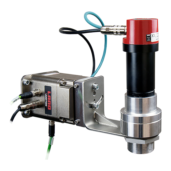
SPOT AL EQS (Aluminium Extrusion, Quench and Strip pyrometer. The SPOT Actuator is a motorised unit which is designed for use at press exit and quench exit positions on aluminium extrusion presses, to align the AL EQS pyrometer with the profile. It is capable of operating in automatic or operator-controlled modes to suit the needs of an individual aluminium plant. -
Page 6: System Components
SPOT Actuator Fixed Spot Thermometers SYSTEM COMPONENTS This section describes the components of the SPOT Actuator system. Before setting up your system, check that you have been supplied with all components. If any components are missing or damaged, contact AMETEK Land Instruments. Item Land Part Nº Notes SPOT Actuator 811824 Mount in a suitable location via the 4 x 8.5 mm... - Page 7 Fixed Spot Thermometers SPOT Actuator Item Land Part Nº Notes Cooling Plate 813374 Used in ambient temperatures exceeding 60 °C / 140 °F to prevent overheating. Positioned between the mounting location and the Actuator it provides optimal cooling capabilities and also acts as a heat barrier.
- Page 8 SPOT Actuator Fixed Spot Thermometers Item Land Part Nº Notes Actuator Ethernet Cable 812033 M12 Ethernet M-F D Coded Cable 0.5 m Used to connect the Actuator to the digital input/output of the pyrometer. Actuator Analogue Cable 812037 0.5 m M-F Analogue Cable...
-
Page 9: Installation
Fixed Spot Thermometers SPOT Actuator INSTALLATION 3.1 Power Requirements CAUTION When first connected to the power supply, the Actuator will move to check the full range of movement. The Actuator can be powered by 18 to 36 V DC or Power over Ethernet (POE+). In each case, a single cable can be used to power and control the actuator. - Page 10 SPOT Actuator Fixed Spot Thermometers The quality of the cooling water has an effect on the life of the probe. The quality of the cooling water should almost be that of drinking water. In the case of contaminated cooling water with insolubles, a water chiller or heat exchange system is strongly recommended. This is also recommended for the sake of environmental protection and cost savings. 3.3.2 Water Temperature The graph below shows different conditions of water temperature and flow rate. The case temperature must be kept below 60 °C / 140 °F (below the red zone). The the Cooling Plate (Part Nº 813374) enables the actuator to be used in air temperatures of up to: •...
-
Page 11: Installation Drawings
3.4 Installation Drawings... - Page 18 Blank...
-
Page 19: Operating Instructions
Fixed Spot Thermometers SPOT Actuator OPERATING INSTRUCTIONS 4.1 Configuring your SPOT Thermometer to work with the Actuator To work with the actuator, the SPOT Thermometer must be running Firmware version 1020 or later. A firmware package is available from www.ametek-land.com. The ‘Scan’ option on the I/O menu of the SPOT thermometer must be set in order for the actuator to be able to switch on the SPOT LED during a scan. -
Page 20: Controlling The Actuator
SPOT Actuator Fixed Spot Thermometers 4.2 Controlling the Actuator The actuator can be controlled in several different ways: Analogue Only (1 cable) The PLC triggers the scan with a 24 V digital signal and reads the 4 to 20 mA temperature signal from the SPOT. Analogue and Remote As above, also local control. - Page 21 Fixed Spot Thermometers SPOT Actuator Ethernet Only (1 cable) Connect to the Actuator for access to both SPOT and Actuator on separate IP Addresses. This allows you to configure all settings, trigger a scan and read scan data using Modbus TCP, or the Actuator Webserver. Ethernet and Remote As above, also local control.
-
Page 22: Control By Plc Using The Analogue Cable
SPOT Actuator Fixed Spot Thermometers 4.3 Control by PLC using the analogue cable The analogue cable must be connected from the control system to the actuator if 24 V digital control or 4 to 20 mA analogue output are required, or to power the unit if Power over Ethernet (PoE) is not available. -
Page 23: Control From The Remote
Fixed Spot Thermometers SPOT Actuator 4.4 Control from the Remote Use the Left and Right arrow buttons to move the actuator. A short press moves it a single step, holding the button down will make it move further. If the direction of movement does not correspond to your application (i.e. pressing the left button makes the actuator appear to move to the right), you can switch the direction in the webserver. -
Page 24: Ethernet Control
SPOT Actuator Fixed Spot Thermometers 4.5 Ethernet Control The Ethernet cable must be connected from the control system to the actuator for Ethernet control and/or Power over Ethernet (PoE). The actuator contains a network switch, so that by connecting to the actuator over Ethernet, it is also possible to connect to the SPOT thermometer either by Modbus TCP or to its Webserver. - Page 25 Fixed Spot Thermometers SPOT Actuator Item Description Temperature Profile display. Double click at a position on the graph to move the actuator to that position. If the direction of movement does not correspond with your application, you can switch the direction from the Display Settings screen (Button 5). SPOT temperature display. Double click on this window to open the SPOT Thermometer’s own webserver interface.
- Page 26 SPOT Actuator Fixed Spot Thermometers 4.5.2 Settings Scan Settings Range The start and end points of the scan are set relative to a nominal zero position at the mid-point of the motor’s range of movement. The scan range is set in steps of 1 degree. The maximum range is 90 degrees e.g. -45° to +45°, you can set the start and end...
- Page 27 Fixed Spot Thermometers SPOT Actuator Remote - In this triggering mode, the scan can is triggered Trigger from either the Handset, the virtual handset on the Actuator Webserver, or via Modbus. Threshold - In this mode, scanning is additionally triggered if the temperature falls below the Threshold value. A profile...
- Page 28 SPOT Actuator Fixed Spot Thermometers Network Mode The network mode can be set to either Static IP or DHCP. If Static IP is set, the Actuator attempts to connect using the configurable IP address set in the box below. If DHCP is set, the Actuator requests an IP address from the network. If no IP address is provided by the network within 30 s, the Actuator attempts to connect with its default IP address of 10.1.10.60. If 10.1.10.60 is already in use on the network, it will...
- Page 29 Fixed Spot Thermometers SPOT Actuator SPOT SPOT Select the type of SPOT thermometer from the drop-down Type list. Note that the ‘Scan’ option on the I/O menu of the SPOT thermometer must also be set to enable correct scan timing.
-
Page 30: Modbus Tcp
0 degrees on the webserver corresponds to Modbus value of 600 for the CurrentPosition and SetPosition registers. All settings and outputs are configured as Modbus Holding Registers, as for the SPOT thermometer. The settings table is shown on the following pages. The SPOT Actuator uses standard Modbus TCP protocol, with messages of the format: Modbus TCP Frame Format Name... - Page 31 Fixed Spot Thermometers SPOT Actuator User Guide 4 - 13...
- Page 32 SPOT Actuator Fixed Spot Thermometers 4 - 14 User Guide...
- Page 33 Fixed Spot Thermometers SPOT Actuator User Guide 4 - 15...
- Page 34 SPOT Actuator Fixed Spot Thermometers 4 - 16 User Guide...
-
Page 35: Maintenance
Fixed Spot Thermometers SPOT Actuator MAINTENANCE To remove power from the Actuator and prevent unexpected movement, disconnect the Digital and Analogue cables from the Actuator to the Control System (shown below). User Guide 5 - 1... -
Page 36: Specification
SPOT Actuator Fixed Spot Thermometers SPECIFICATION Positional Points: 900 points over 90 degrees Speed: Adjustable between approximately 25 ° and 100 ° swivel per second Sealing: IP65 Power Requirement: Power over Ethernet 802.3 at (PoE+) or 18 to 36 V DC 30 W Mounting: 4 holes Dia. 8.5. 109 x 70 pitch Ambient Temperature Range: 5 to 60 °C / 41 to 140 °F... - Page 37 Fixed Spot Thermometers SPOT Actuator Analogue, Ethernet and Optional Remote: Trigger a scan by any method. Also, can be set to scan if SPOT temperature falls below a customer selected value Weight: 3 kg (without instrument and housings) Dimensions: Actuator: 11.5 x 13.0 x 15.5 cm (4.5 x 5.1 x 6.1 in) (without instrument and housings)
- Page 38 AMETEK Land’s global service network provides unparalleled after-sales services to ensure you get the best performance and value from your AMETEK Land products. Our dedicated service centre teams and on-site engineers are trained to deliver the highest standard of commissioning, maintenance and after- sales support.
Need help?
Do you have a question about the SPOT ACTUATOR and is the answer not in the manual?
Questions and answers