Table of Contents
Advertisement
Quick Links
Advertisement
Table of Contents

Subscribe to Our Youtube Channel
Related Manuals for Gossen MetraWatt Camille Bauer CableCop 300

Summary of Contents for Gossen MetraWatt Camille Bauer CableCop 300
- Page 1 Operating Instructions CableCop 300 3.348.736.02 Cable detection system 1/2.96...
- Page 2 Safety notes Caution! Before you use the cable detection system CableCop 300, carefully read these op- erating instructions and follow the generally relevant safety specifications according to DIN VDE while operating the system. When properly used, the safety of both the unit and the user is ensured. Their safety is not ensured, however, if the unit is misused or carelessly handled Before you use an electrical device, always make a performance test to verify that the de- vice is operating properly.
-
Page 3: Table Of Contents
Contents Page Applications, function principle ......... . 4 Description of the units . -
Page 4: Applications, Function Principle
Applications, function principle The cable detection system CableCop 300 permits both electrically dead and live lines in cir- cuits up to 300 V to be reliably detected. An interruption of the power supply, or a discon- necton of equipment containing sensitive electronic parts, is not required. In particular, the following applications are possible: •... -
Page 5: Description Of The Units
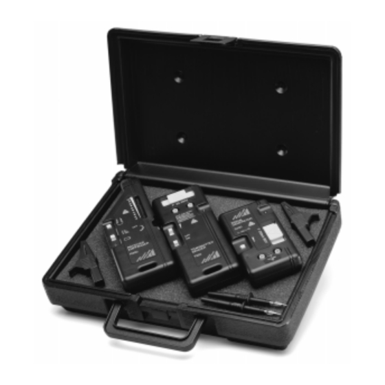
Description of the units 2.1 Receiver R300 The receiver R300 has two built-in detectors which receive the different signals from the sig- nal generator for live and electrically dead lines. These signals are indicated both optically and acoustically: – Optically by a diode assembly with which up to 10 diodes light as a function of the signal strength. -
Page 6: Signal Generator S330 For Live Lines
2.2 Signal generator S330 for live lines The signal generator S330 sends high-frequency electromagnetic signals which the sensor R300 can locate along the line to be tested. For this purpose, the signal generator must be connected to this line as well as to a return line. The signal generator is designed for lines having AC or DC voltages from 9 to 300 V. -
Page 7: Transmitter T320 For Electrically Dead Circuits
2.3 Transmitter T320 for electrically dead circuits The transmitter T320 sends high-frequency electromagnetic signals the electric or magnetic component of which can be detected along the line to be tested by the sensor R300. For this purpose, one socket of the transmitter must be connected to this line. The second socket must be connected to ground. -
Page 8: Measurements On Live Lines With The Signal Generator S330
Measurements on live lines with the signal generator S330 3.1 Closed-circuit mode In this operating mode, live lines are tested with a potential having a maximum of 300 V to ground. The load current normally flows in the phase in opposite direction to the neutral conductor, see connection A. -
Page 9: General Procedures For Live Lines
3.2 General procedure for live lines Signal generator If the measuring circuit has no residual-current circuit breaker, select the highest signal amplification. Caution! Before you connect the signal generator to live lines, verify that not more than 300 V DC or AC voltage are applied. Connect the sockets of the signal generator in line with the application at a time. -
Page 10: Locating Switches, E.g. In Building Installations
3.3 Locating switches, e.g. in a building installation Connection: Connect one socket of the signal generator to the neutral conductor, the other one to the phase of the same socket outlet. Locating: Hold the head of the receiver to every switch in the fuse box. The associated switch is located by the strongest signal. -
Page 11: Locating Short Circuits Between Phase And Protective Conductor Starting From A Switchboard
3.5 Locating short circuits between phase and protective conductor starting from a switchboard Caution! Since voltage could be applied to the lines to be tested, act very carefully: – First find out, whether voltage is applied in spite of the short circuit. –... -
Page 12: Locating Ground Faults In Three-Phase Systems
3.6 Locating ground faults in three-phase systems Caution! Since voltage may be applied to the lines to be tested, act very carefully: – First find out whether voltage is applied in spite of the short circuit. – When testing the voltage with the aid of the standby LED of the signal generator, you always should connect the ground first. -
Page 13: Locating Buried Lines Or Underground Cables Up To A Depth Of Approx. 3 M
3.7 Locating of buried lines or underground cables up to a depth of approximately 3 m Connection: Connect the socket of the signal generator to a separate ground, e.g. di- rectly to an auxiliary earth electrode, the other one to the phase of the line running underground. -
Page 14: Tracing Lines In Conduits
3.8 Tracing lines in conduits Note Note that the magnetic field on the line to be tested can also influence neighbouring conduits. That is why the receiver should be held at least 2 m away from the next switch box. Conduits of steel having thick walls attenuate the signal to be traced while conduits of plastics or aluminium do not impair the signal. -
Page 15: Tracing Coaxial Cables
3.9 Tracing coaxial cables Connection: Connect one socket of the signal generator to the shield of the coaxial cable and the other one to a grounded DC or AC source. Locating: When searching for a line, proceed as described under "General proce- dures for live lines"... -
Page 16: Measurements On Electrically Dead Lines With The Transmitter T320
Measuring on electrically dead lines with the transmitter T320 4.1 Open circuit mode Only lines carrying no current and no voltage must be tested in this operating mode. Connect one output of the transmitter to the line to be tested, the second output to ground. 4.2 General procedures for electrically dead lines Transmitter Install the battery. -
Page 17: Locating Lines And Line Interruptions In Ceilings, Walls And Floors
Open measuring circuits With open measuring circuits, the probe head must be held horizontal to the line as the electric component of the signal is picked up in this case. Closed measuring circuits With closed measuring circuits, the probe head must be held vertical to the line. -
Page 18: Tracing The Entire Building Installation
4.4 Tracing the entire building installation Caution! At first, disconnect the electric system on principle. * Getting started: Remove the bridge between PE and N in the main distribution board. Connection: Connect one socket of the transmitter to PE and the other one to the N terminal in the main distribution board. -
Page 19: Tracing Socket Outlets And Switches Within The Building Installation
4.6 Tracing socket outlets and switches within the building installation Caution! Disconnect the circuit by interruption in the distribution board. Precondition: Neutral conductor and protective conductor each must be connected. Connection: Connect one socket of the transmitter to the protective conductor, the other one to the phase. -
Page 20: Tracing Bottlenecks In Tubing Or Conduits
4.7 Tracing bottlenecks in tubings or conduits Caution! Disconnect existing circuits in the conduit. The circuits must be grounded. Getting started: Disconnect the conduits from the ground connection Connection: Connect one test socket to ground, e.g. to the foundation earth elec- trode or the safety contact of the socket outlet, the other socket to the metal spiral. -
Page 21: Locating Faults On An Electric Floor Heating System
4.8 Locating faults on an electric floor heating system Caution! Make sure that the heating wire to be measured carries neither current nor voltage. Getting started: Interrupt the connection of the shield matting and/or the coaxial shield braiding to ground, if available. Connection: Connect one test socket to ground, e.g. -
Page 22: Locating Underground Lines (Also In The Case Of A Broken Cable)
4.9 Locating underground lines (also in the case of a broken cable) Caution! Make sure that the line to be measured or the circuit to be measured is electrically dead. When using power supplies to increase the performance, only power supplies with safe electrical isolation must be used. -
Page 23: Technical Data
Technical Data 5.1 General information − ° ° Operating temperature C to − ° ° Storage temperature C to 5.2 Receiver R300 Mode selection closed measuring circuit, live line max. 300 V open measuring circuit, electrically dead line Range selection Amplification: x 1, x 10 or x 100 with vernier amplification setting via thumb wheel Battery... -
Page 24: Maintenance
Maintenance 6.1 Battery If the standby LED of transmitter T320 or receiver does not light after turn-on, the battery is probably discharged. A discharged or deteriorating battery must not be left in the battery compartment. Replacing the battery Disconnect the transmitter from the line. Press against the strap of the battery compartment and lift it upwards.
Need help?
Do you have a question about the Camille Bauer CableCop 300 and is the answer not in the manual?
Questions and answers