Table of Contents
Advertisement
Quick Links
Advertisement
Table of Contents

Related Manuals for Beluk KSR-Z

Summary of Contents for Beluk KSR-Z
- Page 1 Technical Documentation Rev. 04 KSR-Z – Capacitor-Bank Protection Relay Technical Documentation Capacitor-Bank Protection-Relay KSR-Z Beluk GmbH Tel.: +49/(0)8861/2332-0 Taubenstrasse 1 Fax: +49/(0)8861/2332-22 D-86956 Schongau E-mail: blr@beluk.de Germany Web: http://www.beluk.de...
- Page 2 Technical Documentation Rev. 04 KSR-Z – Capacitor-Bank Protection Relay Revision history Date Name Revision Change 07.11.11 Initial document release 04.11.15 Password description corrected. Earth fault protection and natural unbalance compensation 10.11.15 descriptions corrected. List of metering values updated. 18.07.18 Content correction...
-
Page 3: Table Of Contents
Technical Documentation Rev. 04 KSR-Z – Capacitor-Bank Protection Relay Contents Section 1: Overview ......................... 4 Section 2: Protection Function and Other Features .............. 5 Section 3: Usage and Main menu ..................11 Section 4: Technical Specifications ..................24 Section 5: Drawings ....................... -
Page 4: Overview
KSR-Z – Capacitor-Bank Protection Relay Section 1: Overview KSR-Z Capacitor Bank protection device has been designed to protect the capacitors from overload, over voltage and unbalance with the advanced and flexible microprocessor technology. A wide range of protection elements are supplemented by advanced features such as control, metering, data storage, fault recorder, remote communications, supervision and self monitoring features. -
Page 5: Protection Function And Other Features
Section 2: Protection Function and Other Features 2.1 Introduction KSR-Z device accepts 4 current inputs and 3 voltage inputs. A full range “Fast Fourier Transformation” is performed on the input data of all channels (3 Voltage channels, 4 Current channels). Thus provides information about the harmonic contents which distort the sine waveform of the current and voltage channels up to 51 order. - Page 6 3 and Appendix B. Samples of the voltage input signals are taken at a frequency of 6,4 kHz. This enables KSR-Z to act as a True RMS measuring device (TRMS) over a wide frequency range.
- Page 7 KSR-Z – Capacitor-Bank Protection Relay 2.2.4 Earth fault protection The KSR-Z calculates the earth fault current as the RMS value of the vector sum from the three currents I . All values are taken from the fundamental wave. EF is compared with two adjustable thresholds, EF trip and EF alarm.
- Page 8 Rev. 04 KSR-Z – Capacitor-Bank Protection Relay 2.2.7 Output contacts KSR-Z relays are available with two types of output contacts two change over contacts four normally open contacts Output contacts are user programmable to operate from protection characteristic, DTL for different protection functions and relay self-monitoring feature (watchdog).
- Page 9 – N and a current signal at current channel 1. This signals are needed get the information of the phase angle and absolute value. 2.3.2 Metering functions The KSR-Z metering features provide continuous measurement of Currents and Voltages which are connected as analogue inputs. The signal processor calculates different values from these inputs. TRMS Voltages V...
- Page 10 50 - 132 VDC. The sensing of the DI can be changed to low active as well. See details at the table at item 3.3.4. 2.5 Trip characteristic With the KSR-Z it is possible to select a adjustable delay time or one of 10 tripping characteristics. For the characteristics please check appendix B. Following trip characteristics are available: C1 = I.E.C.
-
Page 11: Usage And Main Menu
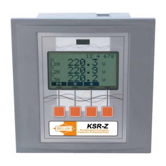
After turning on the supply power, the KSR-Z automatically starts with displaying values of the measurement menu. The key, which is labelled with capital letters „M“ can be used to switch to the main menu. - Page 12 Technical Documentation Rev. 04 KSR-Z – Capacitor-Bank Protection Relay 3.1 Menu “measurement” This menu holds nearly all the measured values. Each value is displayed together with its name (VLN, Ith,... ) and its origin (L1, L2, L3, N). The units of the measured values are also displayed. Use keys „“...
- Page 13 Technical Documentation Rev. 04 KSR-Z – Capacitor-Bank Protection Relay 3.2 Menu “harmonics” All harmonics are normalized to 100% of the fundamental harmonic. Key ““ selects the data source (voltages, currents), ““ and ““ move the display to higher and lower harmonics. The index, which is shown with each harmonic, specifies its order.
- Page 14 Because of the huge amount of setup possibilities, a set of submenus is used. At certain points the user will be confronted with the need to enter numeric values. The KSR-Z will prompt with the old or a default value. One digit of this value will be marked with a “_“ below it. Now this digit can be changed with the „+“...
- Page 15 Technical Documentation Rev. 04 KSR-Z – Capacitor-Bank Protection Relay 3.3.1 Menu “setup->parameter” System parameters: „vt ratio“ - ratio of a VT „ct-I123 ratio“ - ratio of CT for L1, L2 L3 „ct-Iub ratio“ - ratio of a CT for current 4 (unbalance current) ...
- Page 16 This menu contains all MODBUS settings: address - modbus slave address of the device baudrate - data transfer speed over serial RS485 connection parity - parity setting for serial connection For details consult the separate technical documentation for KSR-Z Modbus. Page 16/36...
- Page 17 Technical Documentation Rev. 04 KSR-Z – Capacitor-Bank Protection Relay 3.3.3 Menu “setup->relay” Setup for the relays: „normally open normally closed“ - this selects the relay inversion. If one chooses „normally open“, the relay will be open in inactive state and it will close on activation. “normally closed”...
- Page 18 Technical Documentation Rev. 04 KSR-Z – Capacitor-Bank Protection Relay 3.3.4 Menu “setup->protection settings” The following table gives an overview about the available alarms / trips in KSR-Z which are factory set: Display Protection Operated Relay Store in Blocked Display Auto Man.
- Page 19 To open a input mask us the button. With the KSR-Z it is possible to select a adjustable delay time or one of 10 tripping characteristics by pushing “CURVE” respective “TIME”: For the characteristics please check appendix B.
- Page 20 Technical Documentation Rev. 04 KSR-Z – Capacitor-Bank Protection Relay 3.3.5 Menu “setup ->set password” This submenu allows to change password from factory setting (2402) to customer requirement. If no password protection is required, adjust the password to 0000 no password is required.
- Page 21 FLAGS = options of the device The „M“ - key will switch back to the main menu. To reset the KSR-Z to factory settings, press button 2 & 3 simultaneous. After pressing the buttons the display reading below should appear.
- Page 22 Technical Documentation Rev. 04 KSR-Z – Capacitor-Bank Protection Relay 3.5 Menu “reset alarms” This resets all relays, which are configured with the “manual reset” setting. By selection of this menu entry, the relays are set back to inactive state. A new alarm or trip will re-activate the hold state for the relay.
- Page 23 KSR-Z – Capacitor-Bank Protection Relay 3.6 Menu “fault recorder” The KSR-Z is equipped with a integrated fault recorder. With this fault recorder it’s possible to store each triggered Alarm / Trip event. The fault recorder of the KSR-Z provides 64 memory cells. Each of them stores one Event (ON/OFF).
-
Page 24: Technical Specifications
Technical Documentation Rev. 04 KSR-Z – Capacitor-Bank Protection Relay Section 4: Technical Specifications 4.1 General Performance data according to IEC and VDE standards. 4.2 Current and Voltage Input AC Current Input Rating 1A or 5A (exact rating to be specified... - Page 25 Technical Documentation Rev. 04 KSR-Z – Capacitor-Bank Protection Relay 4.4 Temperature Measuring Temperature (on the rear Probe / Sensor type side) 30°C – 50°C Range 4.5 Settings 55 – 318V +/- 0.5% Settings Line to Neutral 95 – 550V +/- 0.5%...
- Page 26 Technical Documentation Rev. 04 KSR-Z – Capacitor-Bank Protection Relay 4.7 Connections Connections (at the rear Aux. Supply Screw type terminals max. side) 6sqmm rigid, 4spmm flexible Current and Voltage inputs Screw type terminals max. 6sqmm rigid, 4spmm flexible Output Contacts Screw type terminals max.
- Page 27 Technical Documentation Rev. 04 KSR-Z – Capacitor-Bank Protection Relay 4.9 Environmental Withstand 0°C … +70°C Ambient Temperature Operating range -20°C … +85°C Storage range Humidity Operating range 0% to 95% without moisture condensation Overvoltage Category Standards II, pollution degree 3 (DIN VDE...
-
Page 28: Drawings
Technical Documentation Rev. 04 KSR-Z – Capacitor-Bank Protection Relay Section 5: Drawings 5.1 Connection diagram Page 28/36... - Page 29 Technical Documentation Rev. 04 KSR-Z – Capacitor-Bank Protection Relay 5.2 Dimensions Page 29/36...
- Page 30 Technical Documentation Rev. 04 KSR-Z – Capacitor-Bank Protection Relay 5.3 Diagram This diagram shows the set-up for one single alarm. All protection settings work similar. relay 1 threshold relay 2 value 1 relay 4 comparator trigger selection value > value 2...
-
Page 31: Applications
KSR-Z – Capacitor-Bank Protection Relay Section 6: Applications The KSR-Z Capacitor Bank protection device is constructed with a compact case and intended for the protection of capacitor banks. Some applications for the KSR-Z are for example: Detection of over load... -
Page 32: Commissioning Guide
Mount the device in the control panel by means of the two mounting clamps included in the carton. The screw type terminal blocks to connect the KSR-Z device are mounted on the left and right side on the back. The optional connection for the Modbus via RS485 is also mounted on the back. - Page 33 Connect the optional communication interface via RS485 on the backside of the KSR-Z if required. 7.4 Preparation After the KSR-Z device has been installed and connected as described in 6.2 and 6.3 the commissioning procedure can begin. Before turning on the supply voltage, the following items should be checked:...
-
Page 34: Maintenance
KSR-Z – Capacitor-Bank Protection Relay Section 8: Maintenance There is no maintenance necessary for the KSR-Z if you comply with the operating conditions. It is advisable to accomplish a functional test of the device once a year in connection with the regular examination of the system. -
Page 35: Appendix
Technical Documentation Rev. 04 KSR-Z – Capacitor-Bank Protection Relay Section 9: Appendix Appendix A Explanations of the Current damping function for Ith. Ith is a exponentially damped current value to simulate thermal measurement. The formula and the drawings below shall help to understand the Ith function. - Page 36 Technical Documentation Rev. 04 KSR-Z – Capacitor-Bank Protection Relay Appendix B tripping characteristics Trip Curves 1000 Value/ValuePickup Page 36/36...
Need help?
Do you have a question about the KSR-Z and is the answer not in the manual?
Questions and answers