
Summary of Contents for Hillstone ADC
- Page 1 Hillstone Networks ADC Hardware Reference Guide www.hillstonenet.com TWNO: TW-HW-ADC-EN-V1.1-Y20M10...
- Page 2 Note: Not all components in the table are included in one product. This symbol indicates the environment friendly use period of all products and components. The period applies only to the normal operation conditions specified in this guide. Name and Concentration of Toxic or Hazardous Substances and Elements in Products Hillstone...
-
Page 3: Table Of Contents
Connecting the Console Cable ..........................17 Connecting the Ethernet Cable ..........................17 Connecting an AC Power Cable..........................18 ..............................18 ERIFYING NSTALLATION CHAPTER 4 BOOT AND CONFIGURATION ........................20 ................................20 NTRODUCTION ..........................20 CCESSING A EVICE VIA ONSOLE UI ............................20 CCESSING A EVICE VIA Table of Contents Hillstone... - Page 4 ODULE .........................28 NSTALLING THE OWER UPPLY ODULE .........................29 EMOVING THE OWER UPPLY ODULE CHAPTER 6 TROUBLESHOOTING ..........................30 ................................30 NTRODUCTION ..........................30 OSING THE DMINISTRATOR ASSWORD ..........................30 ROUBLESHOOTING OWER YSTEM ......................30 ROUBLESHOOTING THE ONFIGURATION YSTEM COPYRIGHT INFORMATION ........................32 Table of Contents Hillstone...
-
Page 5: Preface
About This Guide Thanks for choosing the Application Delivery Controller (ADC) products from Hillstone Networks, Inc. This document is an installation guide for Hillstone ADC devices to help you install the Hillstone ADC device properly. This guide includes the following chapters: ... -
Page 6: Chapter 1 Introduction
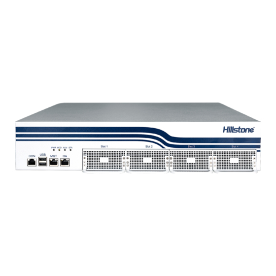
Chapter 1 Introduction Hardware Overview Hillstone ADC devices are designed to fit in standard 19-inch cabinets/racks. A device can be installed in a cabinet/rack or placed on a workbench. Front Panel The front panel of SG-6000-AX4060, SG-6000-AX4060S, SG-6000-AX2000 and SG- 6000-AX2000S consists of 1 Console port, 2 USB ports, 1 Management port, 1 HA port, 4 Expansion slots and several LED indicators. -
Page 7: Expansion Modules
Ethernet2 and Ethernet3 are directly connected. The bypass function is supported on the electrical interfaces of factory standard and is enabled by default. LED Indicators The following table describes the meanings of LED indicators on the front panels of Hillstone ADC devices. -
Page 8: System Parameters
Contact your sales representative if this occurs. As the number and type of LED indicators may vary from different product models, please refer to the actual product. System Parameters The following table lists the system parameters of Hillstone ADC devices of all models. Item Description... -
Page 9: Ports
Voltage SG-6000-AX2000S SG-6000-AX1000 SG-6000-AX1000S SG-6000-AX500 Single Power Ambient Temperature 0℃-40℃ Relative Humidity 5-85% (no dew) Ports This section introduces attributes of interfaces (ports) on the Hillstone ADC devices, including console port, USB port, gigabit copper port, SFP port, SFP+ ports. - Page 10 PC to configure the device. Transmission console cable Medium USB Port Hillstone ADC device provides up to two USB host ports. Attributes for the USB port are shown in the following table. Attribute Description Connector...
- Page 11 The SFP port supports SFP optical module. If you choose to use SFP optical module in SFP port, you should use LC-Type optical connector. Hillstone ADC device supports five types of 1000Base-FX SFP optical modules. All optical modules are hot-swappable.
-
Page 12: Expansion Slot
(provided in the accessory box) over the SFP+ port. Expansion Slot The expansion slot of Hillstone ADC device is a universal interface expansion slot with half-U height. SG-6000-AX4060, SG-6000-AX4060S, SG-6000-AX2000 and SG-6000-AX2000S supports two half-U expansion slots, while SG-6000-AX1000, SG-6000-AX1000S and SG-6000-AX500 supports two half-U expansion slots. -
Page 13: Hard Disk Modules
AX1000S . Hard Disk Modules There is a hard disk module at the bottom of ADC device, whose default storage capacity is 1T (HDD). The hard disk module mainly saves logs to the local and achieves the goals of device monitoring, behavior auditing, etc. The default storage capacity is different on different platforms. -
Page 14: Chapter 2 Installation Preparations
To prevent personnel injury and equipment damage, please carefully read all the safety warnings and cautions in this chapter before the installation. Hillstone ADC devices are designed for indoor use. To ensure the normal operation and to prolong the service lifetime, the installation site must meet the following... -
Page 15: Grounding Requirements
Keep the device away from radio stations, radar, and other high-frequency and high-current devices. Use electromagnetic shielding when necessary. Grounding Requirements To use the device more safely: Ensure that the grounding screw of the chassis is well grounded via the grounding wire. -
Page 16: Installation Devices/Tools/Cables
Installation Devices/Tools/Cables The Hillstone ADC device is shipped with a power cable and a console cable, and you should have the following items before the installation: Terminal: Configuration terminal (e.g. an ordinary PC). Tools: Philips screwdrivers and ESD wrist strap. -
Page 17: Chapter 3 Installation
Before installation, make sure that: You have read Chapter 2 Installation Preparations carefully. The requirements in are satisfied. 错误!未找到引用源。 Hillstone ADC products can be installed: On a workbench On a standard 19-inch rack Tools Cross screwdriver Antistatic gloves Ethernet cable Prerequisite Before installation, make sure that you have taken the ESD prevention measures. -
Page 18: Installing The Device On A Rack
Step 3: Use the cross screwdriver to tighten the screws in the mounting rail assembly until the rail cannot slide. Five screws are provided; arrange the position of these screws on average according to the length of the mounting rail assembly. Step 4: Move the mounting rail assembly aside. - Page 19 Step 2: Attach rack-mounting ears to the left and right side panels of the chassis respectively, and then fasten the rack-mounting ears with screws provided in the accessories. Step 3: Two people are needed to safely raise the device and place it on the tray of the rack or the tray of the mounting rail assemblies.
-
Page 20: Connecting Cables
Connecting Cables This section describes how to connect cables to the device, including connecting the ground wire, the console cable, the Ethernet cable and the power cable. Connecting the Ground Wire To meet safety requirements, you must correctly connect the grounding screw on the chassis to the earth ground by a grounding wire. -
Page 21: Connecting The Console Cable
(also called standard cable) or a crossover cable. The SFP port and SFP+ port use single-mode or multi-mode cables to access Ethernet. All SFP Port and SFP+ Port of ADC products use LC-type optical connector; therefore, you should connect the optical modules using optical fiber ended with LC-type connector. -
Page 22: Connecting An Ac Power Cable
The curvature radius should be greater than 10cm. Avoid excessive bending of the cable. Ensure the Tx and Rx ends are connected correctly. Keep the connector of the optical cable clean. Warning: Laser danger! To protect your eyes from radiation harm, do not stare into a cable connector connected to a laser generator. - Page 23 The grounding wire of the device is correctly connected. The air vents on both side panel of the device are unblocked, and there is enough space around for heat dissipation. The expansion modules, power supply modules and fan tray are correctly installed (for some products).
-
Page 24: Chapter 4 Boot And Configuration
Chapter 4 Boot and Configuration Introduction This chapter describes the initial system boot and basic configuration of Hillstone ADC devices, using a PC as the console terminal. Accessing a Device via Console Port Step 1: Connect one end of the console cable to a computer’s port, and the other end to a device’s console port (labeled CON). -
Page 25: Connecting To The Internet (One-Arm Mode)
Connecting to the Internet (One-Arm Mode) Take the following topology as an example, you can quickly and easily deploy devices to an existing network in one-arm mode. To deploy the device in one-arm mode, take the following steps: 1. Configuring an interface. 2. -
Page 26: Step 2: Configuring A Route
Step 2: Configuring a route 1. Select Network > Routing > Destination Route. 2. Click New, and create a route entry in the pop-up Destination Route Configuration dialog box. Destination: 0.0.0.0 Netmask: 0.0.0.0 Next-hop: Click Gateway. Gateway: 10.1.100.1 3. -
Page 27: Step 6: Configuring Snat
2. Click New, select TCP from the drop-down list, and create "vs_tcp" in the pop-up TCP Virtual Server Configuration dialog box. Name: vs_tcp IP: Port: Select IP Address, and type "10.1.100.100" into the text box; select Port, and type "8888" into the text box, and then click Add. ... -
Page 28: Step 1: Configuring Interfaces And Zones
1. Configuring interfaces and zones. 2. Configuring a VSwitch interface. 3. Configuring a route. 4. Configuring a real server. 5. Binding real servers to a server pool. 6. Binding the server pool to a virtual server. 7. Configuring SNAT. Step 1: Configuring interfaces and zones 1. -
Page 29: Step 4: Configuring A Real Server
2. Click New, and create a route entry in the pop-up Destination Route Configuration dialog box. Destination: 0.0.0.0 Netmask: 0.0.0.0 Next-hop: Click Gateway. Gateway: 10.1.100.1 3. Click OK. Step 4: Configuring a real server 1. Select Load Balance > Server Load Balance > Real Server. 2. -
Page 30: Step 7: Configuring Snat
select Port, and type "8888" into the text box, and then click Add. Server Pool: Select "pool_tcp" from the drop-down list. 3. Click Save. Step 7: Configuring SNAT The gateways of server 1, server 2 and server 3 are deployed on the firewall. In order to ensure consistent traffic in and out, SNAT needs to be configured. -
Page 31: Chapter 5 Hardware Maintenance And Replacement
Chapter 5 Hardware Maintenance and Replacement This chapter explains how to install and remove the power supply module, the expansion module and the daily shutdown of ADC device. Shutdown If you want to shut down your device, take the following steps: 1. -
Page 32: Installing The Expansion Module
Installing the Expansion Module Note: The expansion module is not hot-swappable. Step 1: Make sure the power is switched off and you are wearing the antistatic gloves properly. Step 2: Face the front panel of the device. Step 3: Use a screwdriver to remove the blank panel from the expansion slot. Step 4: Even out the outline of the expansion module and the outline of the expansion slot. -
Page 33: Removing The Power Supply Module
Step 4: Slide the power supply module all the way into the slot cage until you feel resistant. Removing the Power Supply Module Note: Only the dual power device can be installed or removing power supply module. Step 1: Make sure the power supply module to be used is not connected to any supply source. -
Page 34: Chapter 6 Troubleshooting
Chapter 6 Troubleshooting Introduction This chapter provides solutions to some common problems of Hillstone ADC devices. Losing the Administrator Password If you lose the administrator password, please contact your local sales representative. Troubleshooting Power System Check the PWR LED on the front panel of the device. If the power supply is functioning normally, the PWR LED lights steadily in green color. - Page 35 Ensure the terminal configuration settings are correct. If above steps reveal no error, the Console cable may be broken.
-
Page 37: Copyright Information
Hillstone, Hillstone Networks logo, StoneOS, StoneManager, Hillstone PnPVPN, UTM Plus are trademarks of Hillstone Networks. All other trademarks or registered marks are the property of their respective owners. Hillstone Networks assumes no responsibility for any inaccuracies in this document. Hillstone Networks reserves the right to change, modify, transfer, or otherwise revise this publication without notice.
Need help?
Do you have a question about the ADC and is the answer not in the manual?
Questions and answers