
Summary of Contents for Peter electronic VBMS Series
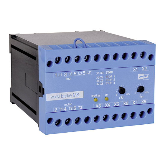
- Page 1 e l e c t r o n i c Combined Motor Start and Braking Device VBMS ... Assembly- and Commissioning Instructions Quality is our Drive.
-
Page 2: Table Of Contents
VBMS ... as per 10/20 1C000.10001 Table of Contents Page Safety notes Conformity General description Usage to the intended purpose EC Declaration of Conformity Block diagram Functional description LED indicators Control inputs 10. Potentiometers 11. Technical data 11.1 Environmental conditions 12. - Page 3 VBMS ... These commissioning instructions were prepared with great care. Nevertheless, PETER electronic GmbH & Co. KG does not assume liability for damage resulting from mistakes possibly contained in this manual. Technical changes that serve to improve the product are subject to change without notice.
-
Page 4: Safety Notes
VBMS ..Safety notes The described devices are electrical equipment for use in industrial electrical power installations. An impermissible removal of the covers during operation can cause serious damage to your health, since these devices contain live parts with high voltages. -
Page 5: General Description
BRMS Usage to the intended purpose The devices of the VBMS series are electrical equipment that is used in industrial power installa- tions. They are designed for an application in machines, in order to switch on and to decelerate drives with three-phase a.c. -
Page 6: Ec Declaration Of Conformity
(authorized representatives of the manufacturer / companies placing the product on the market that are established within the Community) Name / Address: PETER electronic GmbH & Co. KG Bruckäcker 9 92348 Berg hereby declares that the following product (device, component, unit) in the version as supplied... -
Page 7: Block Diagram
VBMS ..Block diagram 5L3 5L3' 24VR 24VR STOP 1 Braking Power supply unit relay STOP 2 STOP 3 Pulse stage Current Motor detection contactor Motor contactor Braking relay Braking Controller relay Motor contactor START Remanence voltage... -
Page 8: Functional Description
VBMS ..Functional description The terminals for the „ON“ or „OFF“-buttons are connected to a 24V extra-low voltage that is physically separated from the mains potential. When actuating the „ON“-button connected with the terminals X1-X2, the integrated motor contactor switches the motor on. If one of the contacts on the terminals X3-X4, X5-X6 or X7-X8 is opened, the integrated motor contactor switches off and initiates braking. -
Page 9: Led Indicators
VBMS ..LED indicators LED - on Operational status Fault correction Illuminated Motor runs Flashing repeatedly motor stillstand Fault will be reset by motor restart with a short pause detected (voltage on T1, T2, T3). Flashing repeatedly Adjusted braking current with a short pause was not reached Flashing... -
Page 10: Control Inputs
VBMS ..Control inputs Control termi- Designation Description nals X1, X2 Starting contact Connection of an „ON“-button (normally open contact) X3, X4; X5, X6; Braking contact Connection of an „OFF“-button (normally closed X7,X8 contact) Warning Please note, the total contact resistance on terminals X3 - X8 of the connected contacts must not exceed 50 Ohm. -
Page 11: Technical Data
VBMS ..Technical data Type designation VBMS 400-2,2/20 230-1,5/20 Ratetd operational voltage 50/60Hz 3x 380/415V 3x 200/240V ±10% according to DIN EN 50160 (IEC 38) ±10% AC-3 Rated operational power 2.2kW 1.5kW AC-3 Rated operational power on IE3 Motor 1.5kW 1.1kW Conventional Thermal current I Braking current... -
Page 12: Commissioning
12.2 Connection The braking device (with integrated motor contactor) is to be installed according to the attached connection diagram. For other connections please consult PETER electronic GmbH & Co. KG. Note: Further connection proposals for special circuit arrangements are available via our homepage at www.peter-electronic.com. -
Page 13: Parameter Settings
VBMS ..12.3 Parameter settings Sequence of steps during commissioning: (the designations/details indicated in brackets refer to the circuit-board version) 1. Disconnect the plant/system from the supply mains. 2. Adjust the requested braking current with the potentiometer „I“, „(P2)“. Since the potentiometer reacts roughly linear, it is possible to infer the braking current from the potentiometer setting. -
Page 14: Possible Fault Indications During Commissioning
VBMS ..12.4 Possible fault indications during commissioning During commissioning, and in normal operation too, fault indications can occur. The following explanation is to give you assistance in the localization and correction of faults. Fault Fault Possible cause Fault correction indication on LED „Ready“, „(V9)“... -
Page 15: Dimensioning Rules
VBMS ..13. Dimensioning rules Note! All data sheets and commissioning instructions are avaialble on our homepage at www.peter-electronic.com. 13.1 Dimensioning of braking device For most applications, it is relatively easy to select a suitable braking device. In most cases, an acceptable braking torque is achieved, if. during braking, the motor is connected in Y (star) and the braking current is 2 times as high as the rated motor current. -
Page 16: Dimensioning Of Pre-Fuses
VBMS ..Calculating the cyclic duration factor (ED): = Braking time = Cycle time (Running-Braking) If the required cyclic duration factor (c.d.f.) exceeds the permissible values indicated on the data sheet, the permissible maximum braking current is to be accordingly reduced. The data required in this connection can be found in the device-specific commissioning instructions. - Page 17 On the basis of the recommended I²t-value, braking current, and possibly the c.d.f., the fuse supplier is able to select a suitable type. Due to the great variety of producers, sizes, and types, PETER electronic does not recommend any particular fuses.
-
Page 18: Permissible Braking Frequency
VBMS ..13.3 Permissible braking frequency The braking frequency depends on the adjusted braking current: Braking current Braking time Braking frequency 1 Braking per 63s 1 Braking per 125s 1 Braking per 34s 1 Braking per 67s 1 Braking per 22s 1 Braking per 44s Warning: When setting up a machine or during commissioning, it is possible to carry... -
Page 19: Dimensional Drawings
VBMS ..14. Dimensional drawings All dimensions in mm. -
Page 20: Typical Connections
EN 61000-6-3:2007 are exceeded. If it is necessary to comply with the limit values of the basic standard EN 61000-6-3:2007, PETER electronic will offer appropriate solutions for the VBMS device series. In this case, please contact us. - Page 21 VBMS ..
Need help?
Do you have a question about the VBMS Series and is the answer not in the manual?
Questions and answers