Advertisement
Quick Links
Version 1.0(2017.12.01)
Humidity & Temperature
Transmitter
www.conotec.co.kr
Instruction Manual
CNT-TM100
취 급 설 명 서
Safety Precautions
1
Please read the instruction manual carefully for correct use.
The speci cation and dimensions provided in the instruction
manual is subject to change without notice for product performance.
Warning!
1. The product is not manufactured as a safety device; therefore, dual
safety devices are required if the product is used as controlling
devices or cases with concern of casualties or serious damage to
the peripheral and signi cant property damage.
2. Do not perform wiring, inspection, and maintenance while power
connected.
3. Terminal numbers must be checked when connecting power.
4. The equipment must not be disassembled, processed, improved, or
repaired.
Caution!
• Please understand how to use, safety regulations, or warnings before the
equipment is installed. The equipment must be used within the provisions
and capacity provided in the manual.
• Do not perform wiring and installation in motors with large inductive load
and solenoid.
• Use the same line when extending sensors and do not use excessive length.
• Do not use parts that create an arc when switching nearby or the same power.
• The power line should be away from high-tension power cables and avoid
installation in areas with high moisture, oil, and dust.
• Avoid installation in direct sunlight and areas exposed to rain.
• Avoid installation in areas with high magnetic, noise, vibration, and impact.
• The equipment should be installed su ciently distant from strong alkali and
strong acid substances.
• When the equipment is installed in the kitchen, do not spray water directly
onto the equipment for cleaning.
• Do not install in places with high temperature/humidity that exceed the rate.
• Care should be provided not to disconnect sensor cables or cause damage.
• Sensor cables require signi cant distance from signal line, power, motive power,
and load line and use independent pipes.
• No warranty service shall be provided if the product has been altered or tampered
with.
• The mark on the wiring terminals is safety statement, such as warning or caution.
• Do not use the product near machines that generate strong high-frequency noise
(high frequency welding machine, high-frequency sewing machine, high-frequency
radios, large SCR controller).
• The product may cause injury or property damage if used for purposes not intended
by the manufacturer.
• Do not leave the product within reach of children as the equipment is not a toy.
• Installation must be performed by professionals or quali ed individual.
• The company shall not be held responsible for any damage caused by negligence of
consumers or due to non-conforming of the warnings or caution statements
aforementioned.
Danger!
Caution, risk of electric shock
Electric shock– Do not contact with AC terminal during current carrying. This may
cause electric shock.
Input power must be blocked when checking input power.
2
Product speci cation
Input power
Display accuracy
12VDC
±1% rdg ± 1 digit
Display method
7 segment 0.51inch 4 Digit 2 Line
Output
(Temperature and humidity) current output 4-20mA
Sensor name
Temperature range
Sensor
SHT - 11
-39.9℃~80.0℃
RS485, MODBUS RTU, Data 8 bit , Parity None , Stop bit 1
Communication
Ambient range
-39.9~80.0℃ , 0~100%Rh
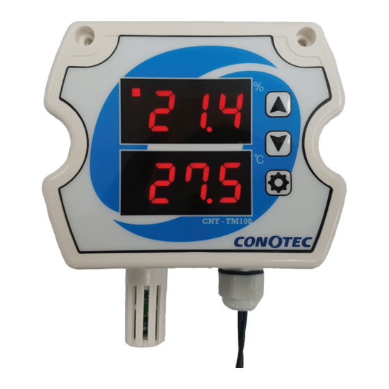
Name of each part
3
Communication state
%
Output state
℃
CNT - TM100
Appearance speci cation and dimension
4
Unit : mm/ Error : ± 0.5
100.00
Ø8.00
Ø3.00
90.00
Terminal connection diagram
5
Current to
mA
Humidity
DC 4~20mA
Current to
mA
Temperature
DC 4~20mA
-
RS485
GND
~
+12VDC
Setting range and default set
6
Setting menu
Classi cation
.
Humidity calibration
.
Sensor heating setting
Humidity
Humidity range
settings
PV transmission
.
20mA humidity
0%~100%Rh
PV transmission
.
4mA humidity
.
Temperature calibration
Temperature
PV transmission
.
20mA temperature
settings
PV transmission
.
4mA temperature
485 communication
address setting
Communication
485 communication
speed setting
Increase switch
Detail description of the function
7
Pressing the
key for 5 seconds in the operation screen will enter the detail
Decrease switch
Change menu by pressing
setting value change
Setting switch
the set value, press
key for 3 or more seconds to save and return to the operation screen.
1
humidity calibration
.
The displayed value can be set to the actual measured humidity when the current
humidity display value and the humidity measured by using a precision instrument
di er.
Example 1) Display value: 5%, the actual measured humidity: 10% => COR +5% input
Example 2) Display value: 5%, the actual measured humidity temperature: 2% => COR -3% input
Humidity sensor heating function
2
.
Dew forms around the sensor devices if humidity is extremely high; hence, the function generates
heat inside the sensor to prevent dew formation if the current humidity is 95% or more.
The heating function operates automatically in 95% or more humidity and the function
is disabled when humidity level is below 95%.
The automatic heating function is not used.
Caution 1. When the humidity sensor heating function is in operation, the current temperature
of the display window may increase slightly.
3
.
.
Humidity setting for 20 mA current output at PV transmit output
.
Humidity setting for 4mA current output at PV transmit output
It is for sending the current humidity to the current output. The humidity range set in H.20 and
H.4 is divided equally and output to 4 - 20mA current.
E.g)
.
current
0%
25%
50%
humidity
4mA
8mA
12mA
4
.
Temperature calibration
The displayed value can be set to the actual measured temperature when the current
temperature display value and the temperature measured by using a precision instrument di er.
Example 1) Display value: 5.0℃, the actual measured temperature: 10.0℃ => COR +5.0℃ input
Example 2) Display value: 5.0℃, the actual measured temperature: 2.0℃ => COR -3.0℃ input
5
.
Temperature setting for 20 mA current output at PV transmit output
.
Temperature setting for 4mA current output at PV transmit output
It is for sending the current humidity to the current output. The temperature range set in T.20
and T.4 is divided equally and output to 4 - 20mA current.
E.g)
.
current
-40.0℃
-10.0℃
20.0℃
temperature
4mA
8mA
12mA
6
RS485 communication address
This is a menu to match an address and the upper system for RS485 communication
7
RS485 Communication speed
This is a menu to match communication speed and the upper system for RS485 communication
120
240
480
: 1200BPS,
: 2400BPS,
: 4800BPS,
Communication description
8
* RS485 MODBUS RTU type protocol is embedded.
Setting range
Default set
* Asynchronous 2-wire half-duplex communication method
* Communication distance: Within 1.2Km
-10.0~10.0%Rh 0.0%Rh
* Communication speed: 1200 / 2400 / 4800 / 9600/ 19200Bps
/
* Start bit: 1 bit, stop bit: 1 bit, parity bit: None, data bit: 8 bit
H.4 ~ 100%
100%
0 ~ H.20%
0%
<Func 0x02 : Read Discrete Inputs>
-10.0~10.0℃
0.0℃
You can receive brief information of status, etc. in a bit form.
T.4 ~ 80.0℃
80.0℃
Request
-40.0 ~ T.20℃
-40.0℃
Start number
Sub
-product
Commend
Upper
1~32
1
address
byte
1BYTE
0x02
1BYTE1BYTE1BYTE1BYTE 1BYTE1BYTE
Response
(9600Bps)
Sub
Number
-product
Commend
of bytes
address
1BYTE
0x02
1BYTE 1BYTE1BYTE 1BYTE
MAP
NO
Address
100001
0000
settings.
<Func 0x04 : Read Inputs Registers>
key 1 time. After adjusting
You can receive simple information, such as current temperature, current
humidity, sensor, and output status.
Request
Start number
Sub
-product
Commend
Upper
address
byte
1BYTE
0x04
1BYTE1BYTE1BYTE1BYTE 1BYTE1BYTE
Response
Sub
Number
Commend
-product
of bytes
address
1BYTE
0x04
1BYTE 1BYTE1BYTE
MAP
NO
Address
300001
0000
300002
0001
300003
0002
300004
0003
Temperature PV transmission output current
300005
0004
Humidity PV transmission output current
<Func 0x03 : Read Holding Registers>
You can read the setting menu.
Request
Start number
Sub
Commend
-product
.
Upper
address
byte
75%
100%
1BYTE
0x03
1BYTE1BYTE1BYTE1BYTE 1BYTE1BYTE
Response
16mA
20mA
Sub
-product
Number
Commend
address
of bytes
1BYTE
0x03
1BYTE 1BYTE1BYTE
<Func 0x06 : Write Single Registers>
You can change the setting menu by one item.
Request
Writing Address
Sub
-product
Commend
Upper
address
byte
1BYTE
0x06
1BYTE1BYTE1BYTE1BYTE 1BYTE1BYTE
.
50.0℃
80.0℃
Response
Writing Address
Sub
16mA
20mA
-product
Commend
Upper
address
byte
1BYTE
0x06
1BYTE1BYTE1BYTE1BYTE 1BYTE1BYTE
960
192
: 9600BPS,
: 19200BPS
Request
Number of data
CRC16
01 02 00 00 00 01 B9 CA
Lower
Upper
Lower
Lower
Upper
Response
byte
byte
byte
byte
byte
01 02 01 00 A1 88
0 0 0 0 0 0 0 0
100001
CRC16
(0000)
Data
Lower
Upper
byte
byte
Sensor open
error
Description
Range
Unit
Output value
Sensor open error
bit0
0: No error, 1: Open error
You can receive simple information, such as current
temperature, sensor status & decimal point, and output status.
Number of data
CRC16
Number of bytes = Number of data * 2
Lower
Upper
Lower
Lower
Upper
byte
byte
byte
byte
byte
Number of data = Five data if ve,
receive 10 bytes
CRC16
DATA 1
DATA n
Upper
Lower
Upper
Lower
Lower
Upper
...
byte
byte
byte
byte
byte
byte
1BYTE1BYTE1BYTE 1BYTE
Range
Unit Output Value
Description
Current temperature
-40.0 ~ 80.0℃
Current humidity
0~ 100.0%
Sensor open error
bit0
0: No error, 1: Open error
4.0mA~20.0mA
4.0mA~20.0mA
Number of data
CRC16
Number of bytes = Number of data * 2
Lower
Upper
Lower
Lower
Upper
byte
byte
byte
byte
byte
Number of data = 23 data if 23, receive 46 bites
DATA 1
DATA n
CRC16
Upper
Lower
Upper
Lower
Lower
Upper
...
byte
byte
byte
byte
byte
byte
1BYTE1BYTE1BYTE1BYTE
DATA
CRC16
If Func.06 Write Single Register
is written normally, the details
Lower
Upper
Lower
Lower
Upper
of Request and Response are
byte
byte
byte
byte
byte
the same.
CRC16
DATA
Lower
Upper
Lower
Lower
Upper
byte
byte
byte
byte
byte
Advertisement

Summary of Contents for Conotec CNT-TM100
- Page 1 Sensor name Temperature range Humidity range Sensor settings PV transmission Instruction Manual H.4 ~ 100% 100% CNT-TM100 20mA humidity SHT - 11 -39.9℃~80.0℃ 0%~100%Rh 취 급 설 명 서 PV transmission 0 ~ H.20% 4mA humidity <Func 0x02 : Read Discrete Inputs>...
- Page 2 Address: 26 Yunsan-ro, Geumjeong-gu, Busan ■ 232-28 Bugok-dong, Geumjeong-gu, Busan Customer Service: +82-70-7815-8266 Inquiry: +82-51-819-0425 ~ 0427 Homepage: www.conotec.co.kr Email: conotec@conotec.co.kr ※ This instrument is suitable in the ■ Major production and development following environment: - Digital temperature/humidity controller - Digital timer, current/ voltage meter Ambient temperature: 0℃...
Need help?
Do you have a question about the CNT-TM100 and is the answer not in the manual?
Questions and answers