
Summary of Contents for Haws 9035
- Page 1 1455 Kleppe Lane Sparks, NV 89431-6467 (775) 359-4712 Fax (775) 359-7424 Website: E-mail: haws@hawsco.com www.hawsco.com No. 0580000867(3) Model 9035 SHOWER SHELTER 12/19 Model 9035 Page 1 of 26...
-
Page 2: Description Of Product
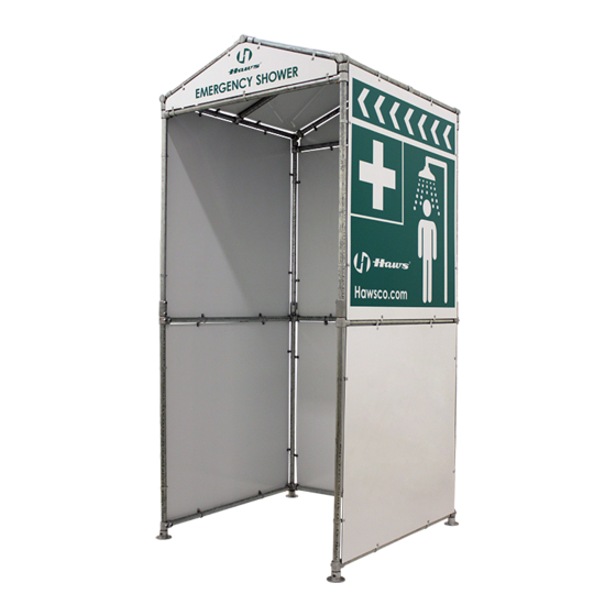
Haws Corporation Model 9035 Shower Shelter (with Privacy Curtain option). Not part of any Certified model. Not Certified on its own. Haws Model 9035 can be installed indoors or outdoors. Its usage intention is weather and privacy protection. SHIPPING, HANDLING AND STORAGE... -
Page 3: Pallet Contents
Appropriate personal protective equipment (PPE) including safety glasses and work gloves. Storage: Unit should be stored in a clean, dry place until ready for installation. PALLET CONTENTS NOTE: Confirm all components listed for the Model 9035 are present before assembly. See Table 1. ITEM NO. PART DESCRIPTION... - Page 4 ON-SITE DELIVERY, HANDLING AND PACKAGE DISASSEMBLY Transport the palletized Model 9035 unit to the installation point via forklift, ensuring the forks are fully inserted through the shipping pallet. The installation area should be a level surface capable of supporting up to 1,000 lbs. spread across a 5 foot by 5 foot area.
- Page 5 Apply thread-locker sparingly at first, to allow for final adjustment and, when final alignment is ascertained, sufficiently coat all screws and lock in place. 9035 SHOWER SHELTER / FINAL ASSEMBLY PREVIEW FIGURE 1...
- Page 6 2X Short Tees 4X 51.00” Pipes 2X 90º Short Elbows 1X 46.12” Pipe 2X Floor Flanges 2X 46.12” Pipes 2X Short Tees 2X Short Tees 2X Floor Flanges FIGURE 2 / Bottom Level Frame Assembly 12/19 Model 9035 Page 6 of 26...
- Page 7 Step 2: Stand the four (4) flange / pipe assemblies from Step 1 on a flat horizontal surface and position them approximately 48” apart. (See Figure 4.) Left 4X Flange / Pipe Right Side Assemblies Side FIGURE 4 12/19 Model 9035 Page 7 of 26...
- Page 8 This allows tool access to the floor mounting hardware. (See Figures 4A & 4B.) 2X Short Tees Flange Mounting Holes Left Front FIGURE 4A Right Front 2X 90º Short Elbows Flange Floor Mounting Holes Left Rear FIGURE 4B Right Rear 12/19 Model 9035 Page 8 of 26...
- Page 9 Step 7: Measure and mark 1 3/4" down from the top of the four 51.00” pipes, with a felt tip marking pen. (See Figure 6.) 4X 51.00” Pipes 1 3/4” From Top of Pipes FIGURE 6 12/19 Model 9035 Page 9 of 26...
- Page 10 Step 11: Fully insert one (1) 46.12" Pipe into the open ends of the rear fittings. (See Figure 7.) (Loosen and re-align the fittings as necessary.) Tighten the elbow set screws Rear Side Right Side Left Side Right Rear 3X 46.12” Pipes FIGURE 7 12/19 Model 9035 Page 10 of 26...
- Page 11 Figure 8 and assembled as described in Steps 12 thru 17. 4X Swivel Tee-Pair (Bottom Halves) 2X 46.12” Pipes 4X Short Tees 4X 45.25" Pipes 4X Straight Couplings (Bottom Level Frame Assembly) FIGURE 8 / Middle Level Frame Assembly 12/19 Model 9035 Page 11 of 26...
- Page 12 – inward - allowing clear access to all set screws. 2X Front Side Straight Couplings Set Screws 2X Rear Side Set Screws Straight Couplings Elbow FIGURE 9A / Right Rear Position FIGURE 9B / Right Front Position 12/19 Model 9035 Page 12 of 26...
- Page 13 Tighten the swivel tee pipe cup set screws. 4X Swivel Tees (Swivel Tee-Pair Bottom Halves) 45.25” Pipes FIGURE 12 FIGURE 12A FIGURE 12B (2X Left Side) (2X Right Side) 12/19 Model 9035 Page 13 of 26...
- Page 14 (See Figure14.) (It may be necessary to loosen the vertical pipe tees in order to properly align the horizontal pipes and tees; If so, do this, re-tighten them, and then tighten the tee pipe cup set screws.) Tees 2X 46.12” Pipes Tees FIGURE 14 ---------------------------------------------------------------------------------------------------- ------------------------------------------------- 12/19 Model 9035 Page 14 of 26...
- Page 15 2X Roof End Supports 2X Roof End Supports (Sub-Assemblies) (Sub-Assemblies) Roof Center Support Roof Center Support (Sub-Assembly) (Sub-Assembly) 3X 49.12” Pipes (Middle Level Frame Assembly) (Bottom Level Frame Assembly) FIGURE 15 / Top Level Frame Assembly 12/19 Model 9035 Page 15 of 26...
- Page 16 (See Figure17B.) 49.12” Pipe Rear Side Swivel Tee Thru Hole & Setscrew Right Side of Unit Rear Side of Unit Roof End Support Right Side Roof Center of Unit Support FIGURE 17A FIGURE 17B 12/19 Model 9035 Page 16 of 26...
- Page 17 (See Figure 19.) Tighten the tee-pair setscrews at the thru holes. 1” Protrusion - Loose End 49.12” Pipe Swivel Tee Thru Hole Swivel Tee (Swivel Tee-Pair Bottom Half) FIGURE 19 (2 Places) 12/19 Model 9035 Page 17 of 26...
- Page 18 (See Figure 22.) Tighten the swivel tee set screws at the 49.12” pipes. 2X Swivel Tee Thru Holes Roof Center Support Roof Center Support FIGURE 22 12/19 Model 9035 Page 18 of 26...
- Page 19 Step 28: Slide the 49.12” pipe to the rear and through the end support swivel tee thru holes. (See Figure 25.) Tighten the setscrews at the roof-top 49.12” pipe. (Re-tighten any loosened set screws.) 49.12” Pipe End Support Thru Holes FIGURE 25 12/19 Model 9035 Page 19 of 26...
- Page 20 (CAUTION: At this stage it is likely that some of the fittings’ setscrews are not fully tightened, and that some fittings and pipes are not-aligned as intended. Therefore, it is highly recommended that steps be taken to square-up, re-tighten & thread-lock the setscrews prior to proceeding with the panel installation. 12/19 Model 9035 Page 20 of 26...
- Page 21 Step 28 / Panel Mounting: All panels must be fastened to the outside of the frame using the mounting hardware supplied by Haws for this unit. This step defines the components and method for attaching the aluminum panels to the frame. (See Figure 27.) Each connection consists of a Screw, Washer, Clamp, and Nut.
- Page 22 (See Figures 31A & 31B.) 1X Slotted Rear Panel 1X Slotted Rear Panel 8X MH Sets FIGURE 31A (View from Front) FIGURE 31B (View from Rear) 12/19 Model 9035 Page 22 of 26...
- Page 23 (See Figures 32A & 33B.) 1X Slotted Rear Panel 2X Plain Side Panels 1X Slotted Rear Panel 1X Slotted Rear Panel 2X Plain Side Panels 8X MH Sets / Panel (24 total sets) FIGURE 32A FIGURE 32B 12/19 Model 9035 Page 23 of 26...
-
Page 24: Limited Warranty
Where claims for defects are made, the defective part or parts shall be delivered to the Company, prepaid, for inspection. HAWS will not be liable for the cost of repairs, alterations or replacements, or for any expense connected therewith made by the owner or his agents, except upon written authority from HAWS, Sparks, Nevada. -
Page 25: Front View
9035 DRAWN: DATE: CHK'D.: REVISION 01/28/19 SHOWER SHELTER APPROVED: DATE: 12/18/19 SCALE: DRAWING TYPE: INSTALLATION SIZE: A SHEET 2019 Haws Corporation - All Rights Reserved. HAWS and other trademarks used in these materials are the exclusive property of Haws Corporation. -
Page 26: Shower Head
9035 DRAWN: DATE: CHK'D.: REVISION 01/28/19 SHOWER SHELTER APPROVED: DATE: 12/18/19 SCALE: DRAWING TYPE: INSTALLATION SIZE: A SHEET 2019 Haws Corporation - All Rights Reserved. HAWS and other trademarks used in these materials are the exclusive property of Haws Corporation.