Table of Contents
Advertisement
Quick Links
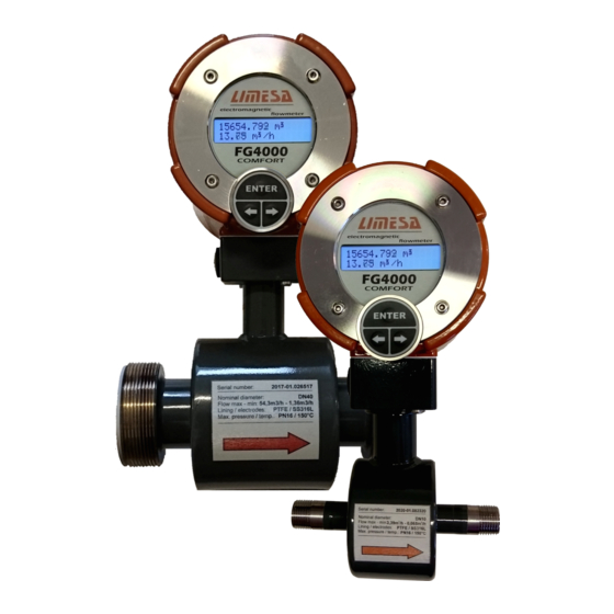
FG4000 – Electromagnetic Flowmeter
Installation and Specifications
Contact informations:
LIMESA meters s.r.o.
Plk. Truhlare 1330
512 51 Lomnice nad Popelkou
Czech republic
Email: info@limesa.cz
http://www.limesa.cz
VATIN: CZ28855159
Tel: +420 602205606
Bank: Ceska sporitelna a.s.
SWIFT: GIBACZPX
IBAN: CZ07 0800 0000 0032 8547 8369
Account no: 000000-3285478369/0800
Advertisement
Table of Contents

Summary of Contents for LIMESA meters FG4000
- Page 1 FG4000 – Electromagnetic Flowmeter Installation and Specifications Contact informations: LIMESA meters s.r.o. Email: info@limesa.cz Bank: Ceska sporitelna a.s. http://www.limesa.cz Plk. Truhlare 1330 SWIFT: GIBACZPX VATIN: CZ28855159 512 51 Lomnice nad Popelkou IBAN: CZ07 0800 0000 0032 8547 8369 Czech republic...
-
Page 3: Table Of Contents
4.15. Unflanged electromagnetic flowmeter gasket dimensions ........8 4.16. Dimensions of unflanged electromagnetic flowmeter ......... 8 4.17. Flanged flowtube sensor dimensions ..............9 4.18. Dimensions of FG4000 electromagnetic flowmeter with threaded connection ..9 Optional temperature sensor location and installation ....10 5.1. -
Page 4: Electromagnetic Flowmeter Installation
FG4000 – installations and specifications 2. Electromagnetic flowmeter installation The assembly of FG4000 flowmeters may only be performed by an organization bearing the authorization certificate to install FG4000 flowmeters based on the training of their accredited staff performed by the manufacturer. -
Page 5: Optimum Liquid Velocity In The Flowmeter Measuring Tube
FG4000 – installations and specifications 4.1. Optimum liquid velocity in the flowmeter measuring tube You should as high liquid flow rate through electromagnetic flowmeter as possible, especially if accurate measurement of flow that fluctuates over a large range of values is required. -
Page 6: Prevention Before Influence Of Sludge Inside The Measuring Tube (Electrodes)
FG4000 – installations and specifications 4.7. Prevention before influence of sludge inside the measuring tube (electrodes) The measuring tube is quite smooth and if the liquid velocity is sufficient as stated in paragraph 4.1, the sludge has no possibility to catch on. If the flow velocity is continuously low with higher occurrence of sludge with heavier specific weight, it is useful to install the flowmeter in sloping or vertical ascending piping (Fig.3 or Fig.5). -
Page 7: Mechanical Installation Of Control Head With The Display
FG4000 – installations and specifications The installation of the inductive flowtube sensor or the flowmeter in compact design should not be launched until all building, welding and painting jobs are completed. Flange seating as in Fig.6 (flowtube sensor shoulder dimensions in paragraph 4.14) provide DN32 to DN100 unflanged flowtube sensor coaxial alignment. -
Page 8: Unflanged Electromagnetic Flowmeter Dimensions
Ø d Fig.14 D d 4.16. Dimensions of unflanged electromagnetic flowmeter FG4000 unflanged electromagnetic flowmeter or split unflanged flowtube sensor installed within a pipe using LIMESA meters installation accessories (Fig.15) Fig.15 Clamping bolts m [kg] B C... -
Page 9: Flanged Flowtube Sensor Dimensions
10, 16 12,5 10, 16 10, 16 10, 16 × Fig. 16b 4.18. Dimensions of FG4000 electromagnetic flowmeter with threaded connection mass G 1" 4.5 kg G 1¼" 6.5 kg ø12 Fig.17a Fig.17b split flowtube sensor compact design FG4000 mtpa –... -
Page 10: Optional Temperature Sensor Location And Installation
FG4000 – installations and specifications 5. Optional temperature sensor location and installation Temperature measurement accuracy and reliability will be guaranteed if you make sure the Fig. 18 following conditions, described in paragraphs 5.1 - 5.3, are met. G1/2“ well 5.1. Temperature sensor installation. -
Page 11: Fg4000 Electromagnetic Flowmeter Connection To Power
In case of the billing meters, the circuit breaker and the junction box should be sealed. 6.2. Safety class FG4000 electromagnetic flowmeter design is in EN 61010-1 safety class I. At the same time it is required that all the flowmeter inputs and outputs should be... -
Page 12: Terminal Bars, Connectors And Jumpers
FG4000 – installations and specifications 7. Terminal bars, connectors and jumpers 7.1. Terminal bars, connectors and jumpers Terminal bars (Fig.22), connectors and jumpers are under the terminal back cover. The terminals can accept wires with the cross section area of 0.8 to 1.5mm . -
Page 13: Connection Of Temperature Sensors To Optional Thermometer Module
(Fig.31) 7.2. Connection of temperature sensors to optional thermometer module FG4000 electromagnetic flowmeter can be equipped with an optional thermometer module with XC1 terminal bar to connect two PT500 (4 wire) temperature sensors. The terminals can accept wires with the cross section area of 0.8 to 1.5mm... -
Page 14: Electromagnetic Flowmeter Pulse Outputs
FG4000 – installations and specifications 7.3. Electromagnetic flowmeter pulse outputs The pulse outputs are performed by optically coupled transistor NPN switches whose Fig. 29 collectors and emitters are connected to the ( + ) and ( – ) terminals respectively. The... -
Page 15: Interface Modules And Archiving Module
FG4000 – installations and specifications 8. Interface modules and archiving module One interface module connected to XC2 (COMM1) can be used with the FG4000 electromagnetic flowmeter. The interface module must be ordered separately. Fig. 32 When connecting the interface module, make sure that all XC2 male pins fit into the corresponding female pins of the interface module's connector (Fig. -
Page 16: Rs485 Interface Module
The F and G pulse input conversion constants may be set independently to follow parameters of F and G input common ( – ) the devices connected in way similar to using E pulse input, which FG4000 electromagnetic flow G input reserved ( + ) meter’s standard feature (paragraph 7.4). -
Page 17: Archiving Module
FG4000 – installations and specifications 8.6. Archiving module We recommend ordering the archiving module simultaneously with the flowmeter since any additional installation may only be performed by a skilled technician. The archiving module is formed by an independent memory and a BT1 clock back-up battery (Fig.22). By default daily and hourly archiving (390 days and 954 hours) is set using the VISIKAL program. -
Page 18: Communication Protocols For Data Collection By Fg4000
FG4000 – installations and specifications 8.7. Communication protocols for data collection by FG4000 Tab. 6 (see also para 9.2) Simple via RS232: 8 bits, no parity, 1 stop bit Transmission to the flow meter: flowmeter identifier byte - total report length = (m +3) volume (m m byte long report –... - Page 19 FG4000 – installations and specifications Modbus RTU via RS485: 8 bits, no parity, 2 stop bits The Modbus RTU communication with FG4000 flow meters is designed only for a reading (writing to the flow meter is not supported). Modbus message format: <DEVICE_ADDRESS><FUNCTION_CODE><DATA (N bytes)><CRC>...
- Page 20 FG4000 – installations and specifications Map of Modbus RTU registers in flow meters FG4000: Parameter Type of data Access 30001 Type of meter, version of FW ASCII STRING (' FG4000 V5.94') Read 30008 Serial number LONG Read 30010 Current flow rate [m3/hour]...
-
Page 21: Empty Pipe Detection
9. Empty pipe detection 9.1. Basic features The FG4000 flow meter can be equipped with the empty pipe detection function. This detection works on the principle of electrical conductivity measurement of the flowing liquid. This function is only relevant for installations where it is not possible to meet the requirement for permanent flooding of the flow sensor (milk, food, chemical industries,...). -
Page 22: Basic Specification, Display
10. Basic specification, display 10.1. FG4000 electromagnetic flow meter basic specifications Design: FG4000 magnetic flow meter has a display and three buttons keyboard. Optionally could be equipped with archive module. The cover of the display unit is made from the aluminium cast and stainless steel front panel. -
Page 23: Fg4000 Flow Meter Display
FG4000 – installations and specifications 10.2. FG4000 flow meter display (alphanumeric backlight LCD, two rows of 16 character) Using a PC with VI SI KAL software installed, it is possible to select any desired data items from the available list ( see next page ) to be shown sequentially on the display when the flow meter button or ENTER is pressed momentarily and repeatedly. - Page 24 FG4000 – installations and specifications Tab. 8 available data list for display Volume 0.001 ... 999999999.999 m 0. 00 . . . 99999.99 m /h or Instantaneous flow rate 0.00 ... 999.99 … 999999.90 l/min Error-free operation time 0 . . . 999999 min...
-
Page 25: User Counters In Fg4000 Flowmeter
ENTER. Items Select ?, Clear ? are not shown on display in such a situation. Notes: FG4000 user counters work independently of whether they are shown on the flowmeter display because reading, resetting and selection of the user counters can be also made via the serial interface module of the flowmeter. -
Page 26: Fg4000 Flowmeter Operating Modes
Bi-directional flow By default, this mode is disabled. If FG4000 is not used for billing purposes, it can be set to bi-directional flow measurement mode. Positive direction of flow is indicated with an arrow on the magnetic flowtube sensor. -
Page 27: Fg4000 Firmware Versions
FG4000 V5. 95 the same version with archiving module. 10.6. Setting menu structure The flow meter FG4000 provides also setting of meter parameters by keypad and display. a) Menu Structure There are 8 main items in the flow meter menu VOLUME OUTPUT COMMUNICAT.PORTS... - Page 28 FG4000 – installations and specifications b) Operation Using Menu An instrument menu is opened by pressing and holding the Enter button for about 2 seconds. Having to enter a PIN prevents from unauthorized access to the instrument menu. The default PIN value is “0000”, which is displayed on entering the menu. If the PIN has already been changed, you need to enter the new PIN.
- Page 29 FG4000 – installations and specifications FG4000 mtpa – rev. 01/2020...
- Page 30 FG4000 – installations and specifications FG4000 mtpa – rev. 01/2020...
-
Page 31: Ordering
Factory setting in accordance with your purchase order specifications prior to shipment is free of charge though. NOTE: FG4000 flow meter Installation dimensions and its features are fully compatible with and can thus be used as replacements for flow meters of EESA company, models FG4000CM , FG4000C, and FG4000E. -
Page 32: Notes
FG4000 – installations and specifications 12. User notes FG4000 mtpa – rev. 01/2020... - Page 33 FG4000 – installations and specifications FG4000 mtpa – rev. 01/2020...
- Page 34 FG4000 – installations and specifications FG4000 mtpa – rev. 01/2020...
- Page 36 LIMESA meters s.r.o. Plk. Truhlare 1330 51251 Lomnice nad Popelkou Czech republic Info@limesa.cz www.limesa.cz...
Need help?
Do you have a question about the FG4000 and is the answer not in the manual?
Questions and answers