
Summary of Contents for LAUREL LAUREATE Series
- Page 1 LAUREATE SERIES SCALE / WEIGHT METER OWNERS MANUAL Now with USB & Ethernet LAUREL Electronics Inc. 3183-G Airway Ave, Costa Mesa, CA, 92626, USA Tel: (714) 434-6131 • Fax: (714) 434-3766 • Website: www.laurels.com...
-
Page 2: Ordering Guide
1. ORDERING GUIDE Configure a model number in this format: LW20201SG1, CBL01 LW ... Laureate scale / weight meter Input Type Process Signals Display Color (4-20 mA, 0-10V, etc.) 1 ......DPM with green LED P ......4-20 mA = 0-100.00 2 ......... -
Page 3: Table Of Contents
2. TABLE OF CONTENTS ORDERING GUIDE ..................... 2 TABLE OF CONTENTS ....................3 PRODUCT INTRODUCTION ..................4 ADVANCED OPERATING FEATURES ............... 5 RECEIVING & UNPACKING ..................6 SAFETY CONSIDERATIONS ..................6 CONNECTOR WIRING INFORMATION ..............7 MECHANICAL ASSEMBLY ..................9 FRONT PANEL SETUP KEYS .................. -
Page 4: Product Introduction
3. PRODUCT INTRODUCTION The Scale Meter is a compact, inexpensive, and extremely accurate digital panel meter with special firmware for weighing applications. It is available with a load cell or a DC signal condi- tioner board. The load cell signal conditioner board accepts full-scale ranges of ±20, ±50, ±100, ±250 and ±500 mV with 4- or 6-wire load cell hookup to display up to 99,999 counts. -
Page 5: Advanced Operating Features
4. ADVANCED OPERATING FEATURES • Setpoint offset. The ON/OFF setpoint control action can be programmed to occur with a specified offset. For instance, if bags are to be filled to 100 lbs and the material delivery spout is known to hold and dispense an additional 2.5 lbs following shut-off, an offset of -2.5 lbs can be programmed. -
Page 6: Receiving & Unpacking
5. RECEIVING & UNPACKING Your scale meter was carefully tested and inspected prior to shipment. Should the meter be damaged in shipment, notify the freight carrier immediately. In the event the meter is not configured as ordered or the unit is inoperable, return it to the place of purchase for repair or replacement. -
Page 7: Connector Wiring Information
7. CONNECTOR WIRING INFORMATION CONNECTORS Connectors for signal and power are UL-rated screw-clamp terminal blocks that plug into mating jacks on the printed circuit board. Communication connectors are a single RJ11 plug for RS232, dual RJ11 plugs for RS485, dual RJ45 plugs for RS485 Modbus, or USB. * Control inputs 1 &... - Page 8 The analog output is sourcing. Do not put an external voltage source in series. Applying an external 24 Vdc source will burn out the analog output board. P3 - SERIAL COMMUNICATIONS P4 - ANALOG OUTPUT...
-
Page 9: Mechanical Assembly
8. MECHANICAL ASSEMBLY REMOVING THE REAR PANEL First remove any connectors. Use one hand to press in the two sides of the rear of the case, and the other hand to press down the two protruding tab releases at the top of the rear panel (see figure below). - Page 10 rear panel. Once the rear panel is in place, reinstall the input/output screw clamp terminal plugs. PANEL MOUNTING Slide the meter into the 45 x 92 mm 1/8 DIN panel cutout. Ensure that the provided gasket is in place between the front of the panel and the back of the meter bezel.
-
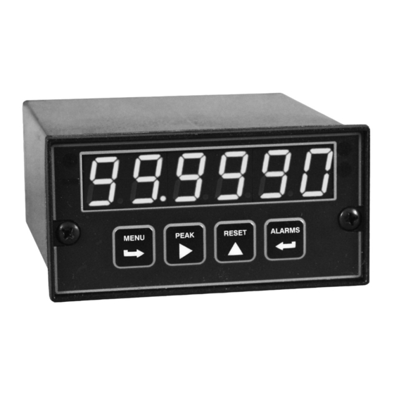
Page 11: Front Panel Setup Keys
9. FRONT PANEL SETUP KEYS Meter Front Panel There are four front panel keys, which change function for the Run Mode and Menu Mode, effectively becoming eight keys. The keys are labeled with alphanumeric captions (MENU, PEAK, RESET, ALARMS) for the Run Mode and with symbols ( right arrow, right triangle, up triangle,... - Page 12 KEYS IN MENU MODE Right Arrow Key (MENU). Pressing steps the meter through all menu items that have been enabled and then back to the Run Mode. With the DC signal conditioner board and no option boards, available menu items are _InPut, SEtuP, ConFG, _FiLtr, dEc.Pt, SCALE, OFFst, 3.
-
Page 13: Enabling & Locking Out Menu Items
10. ENABLING & LOCKING OUT MENU ITEMS For security reasons and ease of meter operation, any or all menu items may be disabled or "locked out" so that they are no longer accessible from the front panel. Each function to be disabled can be set to "1"... -
Page 14: Process & Strain Input Jumpers
11. PROCESS & STRAIN INPUT JUMPERS Process and strain input scale meters utilize the DC signal conditioner board, which offers sensitivity to ±200 mV and can operate in a ratiometric mode, which removes effects caused by variations in the excitation supply. This board needs to be configured via jumpers for the desired voltage or current range. -
Page 15: Load Cell Input Jumpers
12. LOAD CELL INPUT JUMPERS Load cell scale meters utilize the load cell signal conditioner board, which offers sensitivity to ±20 mV full scale and 4- or 6-wire load cell connection. This board needs to be configured via jumpers for the desired voltage range. All signal ranges are factory calibrated with calibration factors stored in EEPROM. -
Page 16: Scale Meter Setup
13. SCALE METER SETUP When the Reading Coordinates of 2 Points scaling method is selected under ConFG, the four menu items below will appear ahead of all other menu items when the MENU or key is first pressed from the run mode. This scaling method applies a straight line fit between two points, which are determined from actual transducer signals and the desired corresponding meter readings. - Page 17 OTHER KEYSTROKES FOR SCALE METER SETUP **If the MENU key does not work, see Section 10 “Enabling & Locking Out Menu Items.” Press Menu Press Digit Press Value Select Select Key Select Key _InPut _dC U __0.2U __2.0U _20.0U 200.0U 600.0U DC signal condi- DC Volts 0.2, 2, 20, 200, 660V FS...
- Page 18 Press Menu Press Digit Press Value Select Select Key Select Key ConFG 00000 Allow negative readings Meter Configuration Negative readings Disallow negative readings 00000 Setup method selected by SEtuP, digit 4 Setup method Reading coordinates of 2 points method 00000 Dribble enabled Dribble function Dribble disabled...
- Page 19 FiLtr 00000 Autofilter Readings Filtering Input signal filtering. Batch avg 60 Hz 50 Hz (continued) Can be applied to dis- Moving avg . 07 s .08 s play, setpoint, analog Moving avg output, data output. Moving avg Moving avg Moving avg 1.13 1.36 Moving avg...
- Page 20 Option board dependent menu items ALSEt. -SP1-d -SP2-d Menu items related to alarm setup These will only appear if a relay board is detected. If so, please see Section 14. AnSEt. Hi.. Menu items related to analog output setup. These will only appear if an analog output board is detected.
-
Page 21: Dual Relay Output Option
14. DUAL RELAY OUTPUT OPTION An optional relay board may be installed in the scale meter main board at plug position P2, adjacent to the power supply board. This board is available in two versions: 2 mechanical relays or 2 solid state relays. Once installed, the relay board is recognized by the meter software and PC-based Instrument Setup software, which will bring up the appropriate menu items for the... - Page 22 00000 After 1 reading After 16 readings Number of consecutive After 2 readings After 32 readings readings in alarm zone After 4 readings After 64 readings to cause an alarm. After 8 readings After 128 reading Press Menu Press Digit Press Value Select Select Key Select Key...
- Page 23 ALARM TYPES Latched alarms stay actuated until reset. They can shut down machinery or a process when a setpoint (or limit) has been exceeded or maintain an alarm condition until acknowledged by an operator. Non-latched alarms change state automatically when a reading rises above a setpoint and change back automatically when the reading falls below that setpoint.
-
Page 24: Analog Output Option
15. ANALOG OUTPUT OPTION An analog board may be installed in the meter at rear panel jack position J4, adjacent to the signal conditioner board. Once installed, this board is recognized by the meter, which will bring up the appropriate menu items for it. These will not be brought up if an analog output board is not installed. -
Page 25: Serial Communication Options
16. SERIAL COMMUNICATION OPTIONS A serial communications board may be connected to the meter main board at plug position P13 (middle position). Available boards are RS232, RS485 (with dual RJ11 connectors), RS485 Modbus (with dual RJ45 connectors), USB, USB-to-RS485 converter, Ethernet, and Ethernet-to-RS485 converter. - Page 26 Basic Ethernet Board No jumpers needed. RS232 Board e - Externally enabled RTS (otherwise always enabled) f - Remote display (or slave) operation. g - Normal operation (other than remote display). Note: Board is shipped with jumper g installed. RS485 Board, Full Duplex Operation b &...
- Page 27 SERIAL CONNECTION EXAMPLES...
- Page 28 KEYSTROKES FOR SETUP If the MENU key does not work, see Section 10 “Enabling & Locking Out Menu Items.” Press Menu Press Digit Select Press Value Select Select Key .SEr __000 Send unfiltered value Fixed Parameters: Output signal source Send filtered value No parity __000U 300 baud...
- Page 29 Press Menu Press Digit Select Press Value Select Select Key .SEr _0000U No line feed after carriage return Serial Setup 2 Line feed Line feed after carriage return _0000U No alarm data Alarm data with readings Alarm data with reading _0000U Continuous data output Control of data output...
-
Page 30: Excitation Output & Power Supply
17. EXCITATION OUTPUT & POWER SUPPLY Three isolated transducer excitation output levels are available from the power supply board. These are selectable via jumpers b, c, d, e, f in the upper right of the board, as illustrated. In addition, the board provides three jumper positions for special features. The same jumper locations apply to the universal power supply (85-264 Vac) and to the low voltage power supply (12-32 Vac or 10-48 Vdc). -
Page 31: Instrument Setup Via Pc
18. INSTRUMENT SETUP VIA PC Instrument Setup software is a PC program which is much easier to learn than front panel programming. It is of benefit whether or not the meter is connected to a PC. With the meter connected to a PC, it allows uploading, editing and downloading of setup data, execution of commands under computer control, listing, plotting and graphing of data, and computer prompted calibration. - Page 32 SETUP OF CONNECTED METER A setup file can be retrieved from the meter (DPM => Get Setup), be edited (View => Setup), be saved to disk (File => Save Setup), be retrieved from disk (File => Open Setup), and be downloaded into one or multiple meters (DPM => Put Setup). Downloading of setup files from a PC can be a major time saving when multiple meters have to be set up in the same way.
- Page 33 Plot Graph • The Readings pull-down menu provides three formats to display DPM data on the PC monitor. Use the Pause and Continue buttons to control the timing of data collection, then press Print for a hardcopy using your PC printer. - List presents the latest readings in a 20-row by 10-column table.
-
Page 34: Scale Meter Calibration
To enter new setup information, click on View => Setup, then make your screen selections as if you were connected to a meter. Tabs will be grayed out if you have not selected the required hardware under the Input+Display tab. When done, press on Main Menu, then on View =>... -
Page 35: Scale Meter Specifications
20. SCALE METER SPECIFICATIONS Meter Display Type ........5 LED, 7-segment, 14.2mm (.56") high digits & 3 LED indicators Color ........................Red or green Range ..............-99999 to +99999 and -99990 to +99990 A to D Conversion Technique (Pat.5,262,780) ................ Concurrent Slope Read Rate ............... - Page 36 DC, Process, Strain Signal Conditioner Range Resolution Resistance Zero Range Span Range Error 200.00 mV 10 V -99999 to 0.01% of FS 2.0000 V 100 V 0 to ±99,999 99999 ±2 cts at 25°C 20.000 V 1 mV Load Cell Signal Conditioner Range Resolution Resistance...
- Page 37 Current Compliance, 0-10V, -10 to +10V Output ....... 2 mA (5 kOhm or higher load) Accuracy .......... Meter input accuracy ±0.02% of full scale analog output Resolution ................... 16 bit (1 part in 65,536) Response Time ..................50/60Hz update rate Scaling of Reading for Zero Output ............-99,999 to +99,999 Scaling of Reading for Full Scale Output ...........
-
Page 38: Glossary Of Terms
21. GLOSSARY OF TERMS Adaptive Filter Threshold A threshold which causes an adaptive moving average filter to be reset to the latest reading when the accumulated difference between individual readings and the filtered reading exceeds that threshold. Adaptive moving average filtering allows a meter to respond rapidly to actual changes in signal while filtering out normal noise. - Page 39 Custom ASCII Protocol A simplified, short protocol for use with these panel meters. It allows 31 digital addresses. Not an industry-standard protocol, like the more complex Modbus protocol, which is also offered with the meters. Display Blank A rear panel input which blanks the display when the input is tied to logic ground by a switch or 0V is applied (logic level true).
- Page 40 Menu Mode The meter programming mode used for input and range selection, meter setup, and meter configuration. Entered into from the Run mode by pressing the MENU key. The Menu mode can be locked out completely by a jumper. Meter Hold A rear panel input which freezes the meter display and all meter outputs while that input is tied to logic ground by a switch or is held at 0V (logic level true).
- Page 41 from the computer. A serial communications option board is required in the meter. If such a board is not installed or no serial data is received, the meter displays rESEt. Reset There are three types of Reset: Peak Reset. Achieved by simultaneously pressing the RESET and PEAK keys.
- Page 42 low input value, and the desired low reading is entered. A known high signal is then applied, such the output of a transducer for a know weight or pressure. That signal is captured as the high input value, and the desired high reading is entered.
-
Page 43: Warranty
In the event of a defect during the warranty period, the defective unit may be returned to the seller, which may be Laurel or a Laurel distributor. The seller may then repair or replace the defective unit at its option. In the event of such a return, freight charges from the buyer shall be paid by the buyer, and freight charges from the seller shall be paid by the seller.
Need help?
Do you have a question about the LAUREATE Series and is the answer not in the manual?
Questions and answers