
Related Manuals for SJE SP6R-X


Summary of Contents for SJE SP6R-X
- Page 1 SP6R-X LEVEL CONTROLLER INSTALLATION INSTRUCTIONS User Manual Manufactured by: SJE Inc. Technical support: +1-800-746-6287 techsupport@sjeinc.com www.csicontrols.com www.primexcontrols.com www.sjerhombus.com...
-
Page 2: Table Of Contents
I/O Terminal Configuration ..........10 SP6R-X I/O Table .............. 11 MODBUS Communication ..........12 MODBUS Registers ............13 Mounting Dimensions ............14 Controller Dimensions ............15 Electrical Wiring Diagram ............ 16 SP6R-X Controller Setpoints List ........17 SP6R-X Controller User Manual ®... -
Page 3: Warnings
Entering incorrect settings may result in damage to equipment. If the SP6R-X controller was shipped pre-installed in a control panel, some default values may have been changed at the factory in order to properly test the control panel operation. The user must adjust the settings... -
Page 4: Introduction And Specifications
INTRODUCTION & SPECIFICATIONS Thank you for your purchase of the SP6R-X controller. This manual explains the features and operations of the SP6R-X controller which was designed to monitor a 4-20mA input signal. The controller features six programmable relay outputs that can be used for control and alarm puposes. -
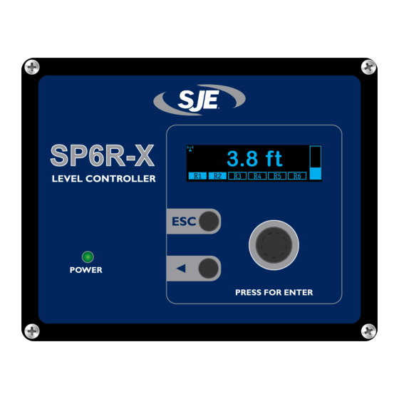
Page 5: Main Screen
PRESS FOR ENTER • Press knob for ENTER or to save settings. Button Returns To Previous Menu Back Button for Stepping Screen, and Exits a Parameter Edit Backward and Changing Value Screen Without Saving Changes. Adjustment Scale. SP6R-X Controller User Manual ®... -
Page 6: Main Menu
Depending on the specific adjustment, hundreds may not be an option. To adjust the scale, click the ◄ button until the desired increment is highlighted. Ones will be adjusted Tens will be adjusted Hundreds will be adjusted SP6R-X Controller User Manual ®... -
Page 7: Level Simulation
This can be helpful for troubleshooting a system to ensure the controller is functioning correctly without actually having various level scenarios available. Rotate the selector knob to make fine adjustments. To make coarse adjustments, press and hold the ◄ button while rotating the selector knob. SP6R-X Controller User Manual ®... -
Page 8: Analog Scaling Menu
Set this value to the displayed level reading that should correspond with the bottom of the bar graph. BAR GRAPH MAXIMUM Set this value to the displayed level reading that should correspond with the top of the bar graph. SP6R-X Controller User Manual ®... -
Page 9: Level Units
(below 3.75 mA or above 20.25 mA). By default, the relay outputs are off (open) when the analog input is out of range. Within the allowable range, the relays operate accord- ing to the relay setpoints. SP6R-X Controller User Manual ®... -
Page 10: Modbus Setup Menu
MODBUS SETUP MENU The Modbus Setup menu contains the following two settings: NODE ADDRESS This is the Modbus address of the SP6R-X. BAUD RATE The Modbus communication baud rate can be set to the following: 1200, 2400, 4800, 9600, 19.2K, 38.4K... -
Page 11: Operation
For an emptying application, the ON setpoint must be greater than the OFF setpoint. For a filling application, the ON setpoint must be less than the OFF setpoint (See below). NOTE: For proper operation of the SP6R-X controller, the ON and OFF setpoints must not be set to the same value. -
Page 12: I/O Terminal Configuration
I/O TERMINAL CONFIGURATION 24VDC IN SHIELD A OUT AO COM +24 VDC SUPPLY AI LEVEL AI COM SHIELD RESERVED RESERVED RESERVED RESERVED RESERVED RESERVED RESERVED RESERVED RESERVED RESERVED RESERVED SP6R-X Controller User Manual ®... -
Page 13: Sp6R-X I/O Table
Protective Earth Ground at terminal PROGRAMMABLE RELAY #4 J1-11 or J1-12. PROGRAMMABLE RELAY #5 Use Copper Conductors, rated 60°C (140°F) PROGRAMMABLE RELAY #6 Apply Torque Value of 4.5 In-lbs to Field Wiring Terminals. SP6R-X Controller User Manual ®... -
Page 14: Modbus Communication
MODBUS COMMUNICATION The SP6R-X is equipped with Modbus RTU support using the D+ and D- RS-485 terminals. The Modbus registers and communications specifi cations are designed to work with an SJE Panel Link Gateway right out of the box. ™... -
Page 15: Modbus Registers
Read/Write 2038 42039 Relay 4 Off Setpoint Read/Write 2039 42040 Relay 5 On Setpoint Read/Write 2040 42041 Relay 5 Off Setpoint Read/Write 2041 42042 Relay 6 On Setpoint Read/Write 2042 42043 Relay 6 Off Setpoint SP6R-X Controller User Manual ®... -
Page 16: Mounting Dimensions
MOUNTING DIMENSIONS Not to scale. Do not use as a template. SP6R-X Controller User Manual ®... -
Page 17: Controller Dimensions
CONTROLLER DIMENSIONS 7.2” 2.5” 6.8” 5.7” 5.3” 5.0” 6.5” SP6R-X Controller User Manual ®... -
Page 18: Electrical Wiring Diagram
ELECTRICAL WIRING DIAGRAM SP6R-X Controller User Manual ®... -
Page 19: Sp6R-X Controller Setpoints List
SP6R-X CONTROLLER SETPOINTS LIST STATION NAME: START UP DATE: CONTROLLER REV: DEFAULT VALUE USER SETTING RELAY SETPOINTS Relay 1 On 999.9 Relay 1 Off 999.9 Relay 2 On 999.9 Relay 2 Off 999.9 Relay 3 On 999.9 Relay 3 Off 999.9... - Page 20 Manufactured by: SJE Inc. Technical support: +1-800-746-6287 techsupport@sjeinc.com www.csicontrols.com www.primexcontrols.com www.sjerhombus.com © 2020 SJE, Inc. All Rights Reserved. PN 1066129B 11/20...
Need help?
Do you have a question about the SP6R-X and is the answer not in the manual?
Questions and answers