Table of Contents
Advertisement
Advertisement
Table of Contents

Related Manuals for DTS NETIMPRESS avant

Summary of Contents for DTS NETIMPRESS avant
- Page 1 Flash Programmer Hardware Manual DTS INSIGHT CORPORATION...
- Page 2 (2) The contents of this manual are subject to change without prior notice due to improvement of the functionality. (3) If any question about the contents of this manual arises, contact DTS INSIGHT CORPORATION. (4) DTS INSIGHT CORPORATION shall not be held responsible for direct or indirect adverse effects resulting from operation of this system irrespective of the above item (3).
-
Page 3: Introduction
NETIMPRESS avant Hardware Manual (hereinafter “manual”) describes specification of hardware of NETIMPRESS avant series products, and the precautions. There is another manual besides this manual for NETIMPRESS avant series products (hereinafter NETIMPRESS avant). – “NETIMPRESS avant Operation Manual”, which describes how to use Please read the manual along with this manual. -
Page 4: For Your Safety
For Your Safety In order to ensure the proper and safety use of NETIMPRESS avant, please be sure to follow the safety precaution mentioned below as operating NETIMPRESS avant. DTS INSIGHT CORPORATION has no responsibility or guarantee for any injuries which occur as a result of the violation of these safety caution and warnings. - Page 5 Action to be taken if abnormality is found NETIMPRESS avant If any failure is found, such as smoke or burnt odor, disconnect and the target. And then turn off the power of main unit. Contact the support center of DTS INSIGHT Corporation.
- Page 6 Confirm the position and direction. Insertion and removal of the Cable Be sure NOT to insert and remove the cable while NETIMPRESS avant is powered on. (Pay special attention to the insertion and removal of the M12 cable between NETIMPRESS avant and the adaptor.) Otherwise, it may cause a serious damage to NETIMPRESS avant and a target system.
-
Page 7: Eu Directive
WASTE ELECTRICAL AND ELECTRONIC EQUIPMENT DIRECTIVE (2012/19/EU) Waste Electrical and Electronic Equipment Directive (WEEE) is for EU countries. NETIMPRESS avant compiles with WEEE Directive (2012/19/EU). Electric/electronic products carrying this mark must be disposed of separately from normal household wastes. Product category: With reference to the equipment types in the WEEE directive Annex 1, this product is classified as a “Monitoring and Control instrumentation”... -
Page 8: Important
NETIMPRESS avant or a target system. Be sure to power on NETIMPRESS avant first. Be sure to power on or off a target system while NETIMPRESS avant is powered on. An incorrect order may result in destroying the circuit of... -
Page 9: Glossary
Glossary Words & Terms Description Micom-pack Package of a parameter file etc. which supports specific MCU. It can be available from our website. Micom-pack is a self-extraction file (EXE file). You can extract the file by double-clicking it. Contents of Micom-pack are Parameter file (.PRM), manuals (.PDF), write control program (.BTP), and readme file etc. -
Page 10: Table Of Contents
4.4. Storage ........................23 5. A ) .................... 24 CCESSORY PTIONAL 5.1. SD card for NETIMPRESS avant ................25 5.2. PROBE HARD ......................26 5.3. Optional cable ......................51 5.4. Accessary ....................... 54 6. FAQ ........................55 Main unit does not work ....................55 7. -
Page 11: Overview And Feature
License sheet is necessary to download a Micom-pack, and definition license, and that license from our website. License sheet is provided when you purchase a definition license. After unpacking, keep the package box contained the NETIMPRESS avant because it will be used at the time of maintenance service for the equipment. -
Page 12: Communication Environments
Setting conditions are stored in the SD card. Therefore you can use it as a stand-alone (without PC). 1.2. Communication Environments Standard Ethernet TCP/IP can be used for communication between NETIMPRESS avant and a host PC. Therefore, a host PC is required to have a corresponding interface. If there is no interface, you need to add it. -
Page 13: General Precautions
(4) In case there is noise in the AC power line, use a noise filter to eliminate the noise. (5) To turn the power on, turn on the power of NETIMPRESS avant first and then a user system. To turn off the power, follow the reverse order. -
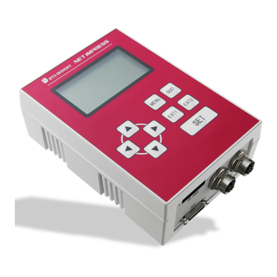
Page 14: Name And Function Of The Components
Displays various information, such as model name of definition program and address etc. This is used when operating NETIMPRESS avant as a stand-alone. Target Connector 1/2 SD CARD Slot This is the connector to Slot for inserting the connect the probe that SD card. -
Page 15: Function Of Components
3.2. Function of Components Function of each key when operating NETIMPRESS avant as a stand-alone 8 keys are used when operating NETIMPRESS avant as a stand-alone. Following table describes function of each key and the behavior. QUIT button is used when you want to stop the operation. -
Page 16: Specifications
4. Specifications 4.1. General Specification Item Specifications Storage environment Ambient temperature -5 to 50℃ Ambient humidity 20 to 80% RH, no condensation Operation environment Ambient temperature 5 to 40℃ Ambient humidity 20 to 80 % RH, no condensation Power Supply Input voltage range AC 100 to 240 V 50 to 60 Hz Consumed power... - Page 17 4.2.3. Target Interface Item Specifications Target connector Type Male/female Female Number of port Pin arrangement Connector pin arrangement (mate side view) Signal Table Table 1: AFX100 Probe Connector Signal List Signal Name definition TX1+ Send data 1 + Output TX1- Send data 1 - Output RX1+...
- Page 18 4.2.4. DIO Interface Item Specifications DIO connector Type HDRA-EA36LFDT-SLE+ (Honda Tsushin Kogyo Co.,Ltd.) Digital output Number of status port 3 (Pass, ERR, RUN) Number general purpose output port Digital input Number script 8 (select from 255 types) selection port Number general purpose port Number of control port...
- Page 19 Pin assignment Type Signal Name Definition (*3) Isolation ground for Digital I/O OUT0 to 4, Pass, 1, 19 DOCOM Error, and Run 2, 20 DOVCC Power supply of overcurrent protection circuit 18, 27, DIVCC Isolation power switch for input PASS status output signal Pass Low: Normal end, Hiz: Other and above...
- Page 20 [Type A] external power supply DC+12 to 24V PS2801C DOVCC + ー voltage conversion Load Pass Error Digital I/O OUT* DOCOM [Type B] PS2805C DIVCC + ー 1.5K external Relay power supply DC+12 to 5.6K HW RST EXT1/EXT2 STEP/START Digital I/O IN1 to 10 [Connection of output signal] Use it by connecting to devices controlled by current drive, such as relay control or LED.
- Page 21 Timing Specifications [EXT1, EXT2] Key entry 1 T T PWL INT Key entry 2 T PWL Minimum T 30 ms 200 ms PWL ∞ T 30 ms INT [Digital I/O INx, Digital I/O STx, STEP, START] Input Minimum ∞ T...
- Page 22 40μs ON → OFF 500μs Input filter setting 1 to 256ms NOTE If you use NETIMPRESS avant with noise sensitive devices, check the actual waveform. Please take adequate actions like shorten the cable or insert a noise filter if needed.
- Page 23 4.2.5. BCR interface Item Specifications BCR Connector Type HDR-EA14LFYPG1-SLG+ (Honda Tsushin Kogyo Co.,Ltd.) Lock screw HDRA-E68LFD-7F Number of port Connector type HDR-EA14LFYPG1-SLG+ (Honda Tsushin Kogyo Co., Ltd.) Pin assignment Signal Definition Name Output 5 V (Max. 500mA for 1 and 6 pin together) Receive input for communication Output 5 V (Max.
-
Page 24: Compliant Standards
EN61326-1 Table2 (For use in industrial locations) RoHS Compliant standards EN 50581 : 2012 4.4. Storage Item Specifications SD card Capacity SDHC Form Full-size SD Interface UHS-Ⅰ Number of port Make sure to use SD card provided by DTS INSIGHT Corporation. -
Page 25: Accessory (Optional)
DTS INSIGHT Corporation. For details of Micom-pack, see the NETIMPRESS ➥ avant startup Manual. If you use other SD cards, NETIMPRESS avant cannot work. Definition license FxX8xx License according to the definition license you use is required. Probe hardware... -
Page 26: Sd Card For Netimpress Avant
5.1. SD card for NETIMPRESS avant 5.1.1. AFM700 型名 概要 AFM700/4G Dedicated SD card(4GB) AFM700/32G Dedicated SD card(32GB) -
Page 27: Probe Hard
5.2. PROBE HARD 5.2.1. PHX400 Dimensional drawing Below shows surface and pins configuration 95(L)×65(W)×25(H)mm 65 ㎜ 2000 ㎜ 300 ㎜ 25 ㎜ 95 ㎜ RDBD-25SE1/M2.6 (55) (Hirose Electric Co., LTD) MC08P2LPG30XSB2 (Cable Force) - Page 28 Signal description(Probe Connector) Signal Name definition RX1+ Received data 1 + Input RX1- Received data 1 - Input TX1+ Send data 1 + Output TX1- Send data 1 - Output Reserved Reserved signal line Reserved Reserved signal line Power Signal description(Serial communication) Below shows description of I/O signal from target side during CSI/UART I/O communication (”I/O”...
- Page 29 Signal description (JTAG communication) Below shows description of I/O signal from target side during JTAG communication (”I/O” means input and output direction from view of probe side.) Signal JTAG Meaning Type Name Mode TCK output of JTAG Transmitted data output of JTAG O(I/O) Received data input of JTAG I(I/O)
- Page 30 Signal description (QSPI communication) Below shows description of I/O signal from target side during QSPI communication (”I/O” means input and output direction from view of probe side.) Signal QSPI Meaning Type Name Mode SCK output of SPI Transmitted data output of SPI SO/IO0 Input / output in dual or quad modes Received data input of SPI...
- Page 31 Signal description (SWD communication) Below shows description of I/O signal from target side during SWD communication (”I/O” means input and output direction from view of probe side.) Signal Meaning Type Name Mode SWCLK SWD CLK output SWDIO SWD data input / output I/O terminal (definition varies according to definition program) I/O terminal (definition varies according to definition program) I/O terminal (definition varies according to definition program)
- Page 32 Signal description (BDM communication) Below shows description of I/O signal from target side during BDM communication (”I/O” means input and output direction from view of probe side.) Signal Meaning Type Name Mode I/O terminal (definition varies according to definition program) BKGD BDM data input / output I/O terminal (definition varies according to definition program)
- Page 33 Interface circuit specification [Type A] 7SZ125 +3.3V (Internal power) LVC244 [Type B] [Type C]...
- Page 34 [Type D] NETIMPRESS side User Target side /TRES、/WDT [Type E] To +XV (To Output Buffer VCC)
- Page 35 [Type F]...
- Page 36 Pin assignment Signal Name Circuit lead Serial mo JTAG mod Type color white white/black TTXD red/black TRXD green green/black TBUSY yellow yellow/black TAUX nTRST brown brown/black TAUX2 blue blue/black TAUX3 orange orange/black TAUX4 grey TMODE grey/black purple purple/black /TICS light blue /TRES light blue/black...
- Page 37 DC characteristics Below shows DC characteristics +TV in the table is power source voltage for output buffer which generated from TVccd. Output voltage fluctuates by voltage drop due to serial resistance in probe and type of input circuit of target system side. Signal Name Item Unit...
- Page 38 5.2.2. PHX401 Dimensional drawing Below shows surface and pins configuration 95(L)×65(W)×25(H)mm 65 ㎜ 2000 ㎜ 300 ㎜ 25 ㎜ 95 ㎜ RDBD-25SE1/M2.6 (55) (Hirose Electric Co., LTD) MC08P2LPG30XSB2 (Cable Force)
- Page 39 Signal description (Probe Connector) Signal Name definition RX1+ Received data 1 + Input RX1- Received data 1 - Input TX1+ Send data 1 + Output TX1- Send data 1 - Output Reserved Reserved signal line Reserved Reserved signal line Power...
- Page 40 Signal description(QSPI communication) Below shows description of I/O signal from target side during serial (QSPI) communication (”I/O” means input and output direction from view of probe side.) Signal QSPI Meaning Type Name Mode SCK output of SPI Send data output of SPI SO/IO0 Input / output in dual or Quad modes Received data input of SPI...
- Page 41 Interface circuit specification [Type A] PHX401 side 7SZ125 (Internal power) VCX244 [Type B] PHX401 side VCX244 [Type C] PHX401 side...
- Page 42 [Type D] User Target side PHX401 side /TRES、/WDT [Type E] PHX401 side To +XV (To Output Buffer VCC)
- Page 43 [Type F] PHX401 side + 2.5V VCX244...
- Page 44 Pin assignment Signal Name Circuit lead QSPI mode Type color white white/black SI/IO0 red/black SO/IO1 green green/black WP#/IO2 yellow yellow/black HOLD#/IO3 brown brown/black blue blue/black TAUX3 orange orange/black TAUX4 grey TMODE grey/black purple purple IO10 /TICS light blue /TRES light blue/black pink/black pink black...
- Page 45 DC characteristics Below shows DC characteristics +TV in the table is power source voltage for output buffer which generated from TVccd. Output voltage fluctuates by voltage drop due to serial resistance in probe and type of input circuit of target system side. Signal Name Item Unit...
- Page 46 AC Characteristics In the case of the target to output when SCK is falling. Parameter Item Criteria Condition This does not depend on the baud Delay time until SO output rate setting. Max. 15ns when SCK is falling. TVCC = 1.8V SCK cycle time Min.
- Page 47 5.2.3. PHX410 Dimensional drawing Below shows surface and pins configuration 95(L)×65(W)×25(H)mm 65 ㎜ 300 ㎜ 2000 ㎜ 25 ㎜ 95 ㎜ RDED-9SE1/M2.6 (55) MC08P2LPG30XSB2 (Hirose Electric Co.,LTD.) (Cable Force)
- Page 48 Signal description(Probe Connector) Signal Name definition RX1+ Received data 1 + Input RX1- Received data 1 - Input TX1+ Send data 1 + Output TX1- Send data 1 - Output Reserved Reserved signal line Reserved Reserved signal line Power Signal description (CAN communication) Below shows description of I/O signal from target side during CAN communication (”I/O”...
- Page 49 Interface circuit specification NET IMPRESS side User target side (internal power) To voltage monitor TVccs circuit [Type B] NET IMPRESS side User target side CANH CANH Relay CANL CANL Configuration circuit of terminating CAN Tr resistance Relay’s initial condition is “OFF” (“OPEN” condition: No terminating resistance).
- Page 50 [Type C] NET IMPRESS side User target side +3.3V (Internal power) TMODE +3.3V (Internal power) [Type D] NET IMPRESS side User target side +3.3V (Internal power) +3.3V (Internal power) Probe Select...
- Page 51 Pin assignment Signal Circuit lead Name Type color TVCCS white CANL black Reserved blue Reserved purple orange CANH yellow TMODE grey PROBE light blue SELECT...
-
Page 52: Optional Cable
5.3. Optional cable 5.3.1. OCX100 (AC code available only in Japan) Cable type differs according to country. For inquiry, please contact your distributor or DTS INSIGHT CORPORATION. - Page 53 5.3.2. OCX110(BCR CABLE) DEB-9P (05) (HONDA TSUSHIN KOGYO CO., LTD.) (Hirose Electric Co.,LTD.) NET IMPRE SS-sid e BC R-sid e Signal Signal Pi n.No Pi n.No name name...
- Page 54 5.3.3. OCX120(DIO Cable) Available for any type of connector. HDRA-E36MA+ (HONDA TSUSHIN KOGYO CO., LTD. Target-side Wiring Specification Pin No. Pin No. Signal Name Insulator Dot Mark color Red 1 dot DOCOM Orange Black 1 dot DOVCC Red 1 dot Pass Grey Black 1 dot...
-
Page 55: Accessary
5.4. Accessary 5.4.1. ACX100(SD card cover)... -
Page 56: Faq
6. FAQ Main unit does not work Check the SD card If the dedicated SD card is broken, NETIMPRESS avant may repeat the start-up operation. In that case, remove the damaged SD card and replace it to the normal SD card. -
Page 57: Contact
7. Contact For inquiry about the specification of NETIMPRESS avant, please contact our support center. For inquiry about the price information or lead time, please contact our sales or your local distributors. Contact NETIMPRESS Support Center E-mail :support-impress@dts-insight.co.jp Shinjuku MIDWEST BLDG. 4-30-3 Yoyogi, Shibuya-ku, Tokyo, 151-0053, Japan...
Need help?
Do you have a question about the NETIMPRESS avant and is the answer not in the manual?
Questions and answers