
Summary of Contents for HSP STARIS Sia+
- Page 1 Installation, operating and maintenance instructions Transformer bushing Range STARIS®-Sia+ Version 01 11/20 en-US...
-
Page 2: Table Of Contents
Contents Documentation notes..............5 How the text is displayed in this document............5 1.1.1 Descriptions.......................5 1.1.2 Instructions........................ 5 1.1.3 Cross-references....................... 5 1.1.4 Lists........................... 5 1.1.5 Additional applicable documents................5 Storage of documents.................... 6 Validity of instructions................... 6 Target groups......................6 Safety................... - Page 3 5.1.2 Slinging the bushing....................20 5.1.3 Putting the bushing down..................23 5.1.4 Component overview (draw lead bolt / detachable conductor bolt)......23 5.1.5 Removing the draw lead bolt / detachable conductor bolt........25 5.1.6 Mounting the electrode on the transformer side (option)........27 5.1.7 Cleaning the bushing....................
- Page 4 Huge damages.......................49 Storage..................50 Standard storage....................50 Long-term storage....................50 Disposal..................51 10.1 Constituent parts of the bushing................ 51 Standard torques..............52 11.1 Standard torques....................52 11.2 Standard torques for air release screws............52 Range STARIS®-Sia+ 4/53...
-
Page 5: Documentation Notes
Documentation notes The following describes how the text is presented and to whom the instruction applies. How the text is displayed in this document 1.1.1 Descriptions Descriptions are normal running text. 1.1.2 Instructions ► Instruction Sub-instruction ▷ → Reaction of product to instruction 1.1.3 Cross-references Chap. -
Page 6: Additional Applicable Documents
■ All instruction manuals included with the product ■ The associated bushing specification ■ The transformer manual (not part of HSP scope of supply) Storage of documents This documentation and all its associated applicable documents must be stored in the vicinity of the product and be accessible to the personnel. -
Page 7: Safety
Safety The following safety information applies for the entire instructions. Classification of the handling-relevant warning instructions DANGER This warning instruction indicates a dangerous situation, which will inevitably lead to a severe or fatal accident if it is disregarded. ► Handling instruction for danger defense WARNING This warning instruction indicates a dangerous situation, which may lead to a severe or fatal accident if it is disregarded. -
Page 8: General Safety Instructions
Intended use includes: ● observance of all product instructions and instructions concerning the components of the installation ● operation of the product without changes to the product ● operation of the product within the specified operational limits (see bushing specification) ●... -
Page 9: Crush And Impact Danger From Suspended Loads
2.3.2 Crush and impact danger from suspended loads There are injury dangers from suspended loads (lifted bushings etc.). ► Be aware of uncontrolled movements of the loads with lifted bushings. ► Never work under a suspended bushing. Obligations of the integrator/operator The integrator/operator has the following supervisory obligations: ●... -
Page 10: Action In The Event Of An Accident
The integrator/operator must ensure the qualification of the personnel. Personal protection equipment The integrator/operator is responsible for the provision of appropriate personal protection equipment. HSP recommends: Protective clothing Hearing protection Range STARIS®-Sia+ 10/53... - Page 11 Head protection (safety helmet) Eye protection (safety goggles, possibly close-fitting) Hand protection (for protection from mechanical and chemical dangers) Foot protection (safety shoes) For additional Additional appropriate protection equipment special local dangers Range STARIS®-Sia+ 11/53...
-
Page 12: Structure
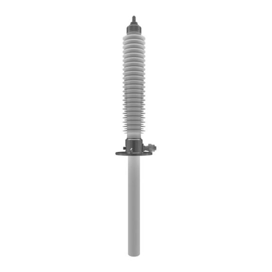
Structure The chapter describes the structure and design of the bushing. General structure Fig. 1: Structure of the bushing Item Part Item Part Connection terminal outdoor side Flange Head Insulating body Isolator Connection transformer side Range STARIS®-Sia+ 12/53... -
Page 13: Version With Draw Lead Bolt Or Detachable Conductor Bolt
3.1.1 Version with draw lead bolt or detachable conductor bolt Fig. 2: Version with draw lead bolt or detachable conductor bolt 3.1.2 Version with undetachable conductor bolt Fig. 3: Version with undetachable conductor bolt Range STARIS®-Sia+ 13/53... -
Page 14: Design
Design Fig. 4: Bushing design (example) Range STARIS®-Sia+ 14/53... - Page 15 Item Part Item Part Hexagon screw Transformer vent (not shown → on the back of the flange armature) Air release screw Insulating body Composite insulator Central tube (draw lead or detachable conductor bolt) Flange armatures Aluminum foil Measuring connection/voltage splitter Polyurethane-elastomer connection Sling points...
- Page 16 ● A test tab (5) ● Sling points (6) ● Grounding screw (7) ● Lift-off screws (8) ● Transformer vent (10) Bushing head The clamping piece (16) is screwed to the head armature of the composite insulator. Seals (17) are arranged in defined chambers in the interface between the pin and the clamping piece.
-
Page 17: Technical Data
Technical data Standard values are stated in the technical data. ► Always observe the bushing specification applicable to the bushing for the product-specific values. General operating conditions Classification (STARIS®- STA Standard Sia+) RIS Resin impregnated synthetic Sia Silicone insulator (ANSI Standard) New product generation Ambient temperature Outdoor side: -30 …... -
Page 18: Mechanical Stress
Standard packaging In heat-resistant wooden crate (or equivalent material). Carried in bearing shells. Sealed in film with addition of dry filling. Mechanical stress Test bending load Standard, in accordance with IEEE C57.19.00 and IEEE C57.19.01 Operating load 50 % of test bending load Range STARIS®-Sia+ 18/53... -
Page 19: Installation
Installation The chapter covers the preparation, execution and post-treatment of the installation. NOTICE Material damage caused by mechanical stress The bushing can suffer damage (particularly to the porcelain or silicone insulators) from mechanical stresses. ► When installing, make sure that the bushing is not exposed to mechanical stresses (particularly to porcelain or silicone insulators). -
Page 20: Checking The Scope Of Supply
■ Sealed in film with addition of dry filling ■ For larger bushings: Flange supported with wooden cross beams ► If a data logger is included in the scope of supply, then provide the HSP data of the data logger. -
Page 21: Slinging The Bushing
5.1.2 Slinging the bushing If the bushing needs to be prepared specially (e.g. with a draw lead bolt or detachable conductor bolt, or if an electrode needs to be installed), the bushing must be put down on bearing supports for preparation. NOTICE Material damage by lifting the bushing improperly If a bushing with silicone insulator is lifted up on the insulator, the sheds may suffer... - Page 22 Fig. 6: Lifting with two lifting devices (example illustration) Threaded bores for removable ring screws are provided at the outdoor side end (either in the connecting bolt or in the head flange). Sling points are cast into the flange, but they may be provided as ring screws for threaded bores (ring screws included in scope of supply).
-
Page 23: Putting The Bushing Down
5.1.2.2 One lifting device (crane etc.) ► Attach lifting accessories from crane shackle to flange. ► Suspend a pulley to the same shackle. ► Guide the lifting accessories on the pulley to the bushing head. ► Tighten the pulley until the length of both lifting accessories is such that the crane shackle is positioned above the center of gravity of the bushing. -
Page 24: Component Overview (Draw Lead Bolt / Detachable Conductor Bolt)
5.1.4 Component overview (draw lead bolt / detachable conductor bolt) Fig. 7: Detachable parts of the bushing head Item Part Item Part Draw lead bolt / detachable conductor Clamping piece bolt Clamping screw O-ring Fixing screws Range STARIS®-Sia+ 24/53... -
Page 25: Removing The Draw Lead Bolt / Detachable Conductor Bolt
5.1.5 Removing the draw lead bolt / detachable conductor bolt The bushing is delivered either with the draw lead bolt / detachable conductor bolt still installed or with it already removed (in the crate lying next to the bushing). If the bushing has an installed draw lead bolt / detachable conductor bolt, the draw lead bolt / detachable conductor bolt can be removed. - Page 26 Fig. 9: Removing the draw lead bolt / detachable conductor bolt (2) Item Part Item Part Draw lead bolt / detachable conductor bolt ► Drive the draw lead bolt / detachable conductor bolt (1) into the bushing using light blows with a rubber hammer.
-
Page 27: Mounting The Electrode On The Transformer Side (Option)
5.1.6 Mounting the electrode on the transformer side (option) As an option, the bushing can have an electrode (see bushing specification). If there is an electrode provided on the bushing, it must be mounted on the electrode holder. Fig. 10: Structure of an electrode holder (here as an example with agile inner disk) Item Part Item... - Page 28 If you continue to turn, the pins engage in the fastening slits. ► To simplify mounting of the current connections, slide the electrode over the two discs on the electrode holder through the relevant apertures before putting in place. Range STARIS®-Sia+ 28/53...
-
Page 29: Cleaning The Bushing
5.1.6.1 Mounting the electrode NOTICE Broken electrode pins If too much force is exerted during mounting, the pins on the electrode may break off. ► Always mount the electrode carefully, never use excessive force. ► Place the electrode opposite the electrode holder so that the pins are located opposite the openings in the disc. -
Page 30: Connecting Draw Lead Bolt / Detachable Conductor Bolt To The Transformer Connection (Option 1)
WARNING Danger of injury caused by prohibited inclined tensile force In the event of exceeding the permitted angle for the inclined tensile force, screwed sling points can be ripped off the bushing and persons may suffer injury. ► Select the lengths of the two lifting accessories so that the permitted inclined tensile force is not exceeded (60°... -
Page 31: Mounting The Detachable Conductor Bolt (Option)
5.2.4 Mounting the draw lead bolt (option) Fig. 11: Mounting the draw lead bolt Item Part Item Part Draw lead bolt Pulling wire/pulling rod ► Lower the bushing slowly onto the transformer. NOTICE Material damage caused by pulling elements being too big If the pulling elements (pulling wire or pulling rod) are too big, the O-rings may suffer damage when the draw lead bolt is pulled through. -
Page 32: Mounting The Head Armature Of The Bushing (With Draw Lead Bolt / Detachable Conductor Bolt)
5.2.5 Mounting the detachable conductor bolt (option) Fig. 12: Mounting the detachable conductor bolt Item Part Item Part Detachable conductor bolt Suitable lifting equipment ► Screw a pulling rod into the drilled hole on the face side of the detachable conductor bolt. ►... - Page 33 5.2.6 Mounting the head armature of the bushing (with draw lead bolt / detachable conductor bolt) Fig. 13: Draw lead bolt / detachable conductor bolt (1) Item Part Item Part Second wave-form groove Draw lead bolt / detachable conductor bolt First wave-form groove The draw lead bolt is conical.
-
Page 34: Connecting Undetachable Conductor Bolt To The Transformer Connection (Option 2)
Fig. 14: Mounting the draw lead bolt / detachable conductor bolt (2) Item Part Item Part Clamping screw Locking screw ► Screw in the locking screw (2) and the clamping screw (1). Chap. 11.1 ► Tighten the locking screw to the stipulated torque value ( on page 52). - Page 35 5.2.7.2 Pushing the electrode through To simplify mounting of the current connections, the electrode can be slid over the two discs on the electrode holder before putting in place. Fig. 15: Pushing the electrode through Item Part Item Part Pins Cut-outs ►...
-
Page 36: Screwing The Bushing To The Transformer
Screwing the bushing to the transformer ► To install the bushing (including tightening the fixing screws and sealing the bushing [sealant not in scope of supply of HSP]): ■ Observe the transformer manual. ■ Observe the operating standard torques ( Chap. -
Page 37: Post Installation Tasks
Post installation tasks ► Carry out the concluding work of the installation. 5.3.1 Releasing the ring screws Prerequisite: The lifting eyes are ring screws. ► Unscrew the ring screws from the threaded bores. ► Mount the plastic covers on the threaded bores. Range STARIS®-Sia+ 37/53... -
Page 38: Preparation For Commissioning
Preparation for commissioning The chapter covers activities and tests before commissioning. Filling the transformer As long as the operating temperature of the bushing is not exceeded, the transformer can be evacuated for any desired period (if necessary). ► If necessary, evacuate the transformer. ►... -
Page 39: Check Bushing
► In order to remove air bubbles under the bushing flange, open the air release screw flange (3) so that the air can escape (partial unscrewing of the screw will suffice). The screw (2) serves to fill the bushing with dry filling. It must never be opened. ►... - Page 40 Appropriate reference data will already be available if a reference measurement has been carried out during the final acceptance tests. ► Carry out a reference measurement of the bushing on site in order to be able to compare Chap. 7.3 later measurements (identical measuring conditions) ( on page 43).
-
Page 41: Maintenance
Maintenance The chapter describes the activities and tests for maintenance of the bushing. Maintenance schedule Maintenance work Interval Described in ... Check and clean insulator Chap. 7.2 Check: Annually or on page 41 surface together with transformer- maintenance Cleaning: Only with acute necessity Check bushing electrically Chap. - Page 42 Fig. 17: HC classification The HC classification provides an approximate statement concerning the water repellent features of the composite insulator. The HC classification is simply a rough comparative procedure and does not permit any statement of a guaranteed operating performance. ►...
-
Page 43: Check Bushing Electrically
NOTICE Material damage from too frequent cleaning of the insulator surface Cleaning greatly changes the water repellent property of the insulator surface. The insulator surface gets its water repellent property back approximately 1 ... 2 days after cleaning. If cleaning is too frequent, the water repellent property is reduced over the long- term. -
Page 44: Measuring Equipment
7.3.1 Measuring equipment ► Use appropriate measuring equipment or contact HSP. 7.3.2 Measuring procedure The measuring procedure differ by the coupling of the measuring signal: ● With not grounded measurements, the test voltage is applied to the conductor on the bushing and the measuring signal is taken from the test tab on the bushing. - Page 45 Fig. 19: ΔC/ΔC Axis Meaning Voltage U of the bushing Change of capacity ΔC/ΔC depending on the voltage U ► If the capacity deviation indicates partial breakdowns, then: ▷ Take the bushing out of service. ▷ Contact HSP. Range STARIS®-Sia+ 45/53...
-
Page 46: Test Tab
7.3.4 Test tab Fig. 20: Test tab Item Part Item Part Grounding contact Test tab O-ring Insulated bushing with pin Removable cap The last grading layer of the capacitive grading is directed out using the test tab (4) (insulated bushing (5)). The removable cap (3) has an o-ring seal (2) to ensure that the inner space of the test tab remains free from humidity. -
Page 47: Voltage Tap
7.3.5 Voltage tap All bushings in the range Sia+ having a nominal voltage greater than 69 kV have a voltage tap. Fig. 21: Voltage tap (example illustration) Item Part Item Part Insulated bushing with pin Removable cap Voltage tap Grounding contact Oil filling hole O-ring The penultimate grading layer of the capacitive grading is directed out using the voltage tap... -
Page 48: Check The Temperature Using A Thermal Image
► With an increase of temperature greater than 40 K or with over temperatures under low load, check the contacts. Hotspots over the outdoor insulator length can cause a nonuniform temperature distribution. ► Make a more detailed investigation of possible hotspots (possibly contact HSP ). Range STARIS®-Sia+ 48/53... -
Page 49: Repair
► In the event of damage, first contact HSP (quoting the serial number of the bushing). ► Discuss the next steps with HSP in the event of smaller or larger damage to the bushing. Smaller damages ►... -
Page 50: Storage
● Storage in protected dry rooms ● Bushing stored in original packaging (plastic film) (with dessicant bags inside) ● Protection from direct sunlight HSP recommended additional mechanical protection of the active section with a HSP protection tank (coated steel). Fig. 22: Protection tanks (example illustration) ►... -
Page 51: Disposal
Disposal The constituent parts of the bushing are non-toxic, not self-inflammable and not physically burdening. They can be disposed of as industrial waste. 10.1 Constituent parts of the bushing The bushing contains: ● Conductor bolt: Cu-ETP or Cu-HCP ● Insulating body: Epoxy-resin impregnated synthetic fleece with aluminum foils ●... -
Page 52: Standard Torques
Standard torques The standard torques apply to: ● Screw connections with stainless steel screws ● Flange connections with O-ring seals and metallic contact of the parts 11.1 Standard torques Screw Torque [Nm] Torque [kpm] 1.10 0.11 2.20 0.22 4.00 0.40 10.00 1.00 19.00... - Page 53 11/20 Tel: +49 (0) 22 41/25 26-0 The required technical options should therefore Brands and trademarks used in this Fax: +49 (0) 22 41/25 26-116 be specified in the contract. document are the property of HSP Email: contact@hspkoeln.de Hochspannungsgeräte GmbH.
Need help?
Do you have a question about the STARIS Sia+ and is the answer not in the manual?
Questions and answers