Table of Contents
Advertisement
Advertisement
Table of Contents

Summary of Contents for Lovato EASY FAST SMART
- Page 1 Installation Manual Revision 0 January 2010...
-
Page 2: Table Of Contents
1.0 GENERAL RECOMMENDATIONS ................page 2.0 CONNECTION OF THE INJECTORS CUT-OFF WIRING..........page 3.0 EASY FAST SMART 3-4 CYLINDER LPG PNEUMATIC DIAGRAM ......page 4.0 EASY FAST SMART 3-4 CYLINDER CNG PNEUMATIC DIAGRAM ......page 5.0 EASY FAST SMART 3-4 CYLINDER LPG WIRING DIAGRAM ........page 6.0 EASY FAST SMART 3-4 CYLINDER CNG WIRING DIAGRAM ........ -
Page 3: General Recommendations
If the fuse blows, do not replace it with one of a higher current rating. • Do not attempt to open the control unit as this could cause irreparable damage. LOVATO decli- nes all liability for injury to people or damage to property should its equipment be tampered with. -
Page 4: Connection Of The Injectors Cut-Off Wiring
INDEX 2.0 CONNECTION OF THE INJECTORS CUT-OFF WIRING. Verify the polarity of the injectors acting as follows: Disconnect all connectors of the original injectors, Prepare a multimeter to measure the direct voltage with full range equal to 20V and connect the negative lead to the ground, Place the positive lead on one of the contacts of the connector injector, Insert the panel and check on the multimeter the measured voltage value. -
Page 5: Easy Fast Smart 3-4 Cylinder Lpg Pneumatic Diagram
INDEX 3.0 EASY FAST SMART 4 CYLINDER LPG PNEUMATIC DIAGRAM 4.0 EASY FAST SMART 4 CYLINDER CNG PNEUMATIC DIAGRAM INDEX... -
Page 6: Easy Fast Smart 3-4 Cylinder Lpg Wiring Diagram
INDEX 5.0 EASY FAST SMART 4 CYLINDER LPG WIRING DIAGRAM 6.0 EASY FAST SMART 4 CYLINDER CNG WIRING DIAGRAM INDEX... -
Page 7: Operation Of The Switch
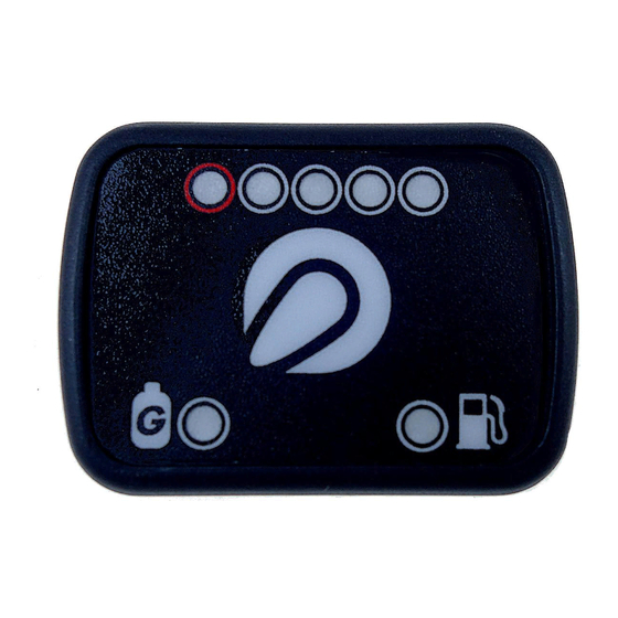
INDEX 7.0 OPERATION OF THE SWITCH The switch supplied with the kit is equipped with a push-button, 7 luminous LEDs, and an internal buz- zer. ITEM DESCRIPTION Changeover switch [ORANGE LED] Car running on petrol [GREEN LED] Car running on gas and diagnosis indicator [RED LED] Reserve [GREEN LEDs] Quantity of gas in the tank PUSH-BUTTON... - Page 8 INDEX EMERGENCY Should the car not be able to start with petrol feeding (e.g. due to problems on the petrol pump, etc.), it is possible to start it directly with GAS feeding. To do this, just start the car keeping the switch push- button pressed.
-
Page 9: Easy Fast Interface Software
INDEX 8.0 EASY FAST INTERFACE SOFTWARE 8.1 MINIMUM REQUIREMENTS OF THE COMPUTER TO INSTALL THE SOFTWARE Operating system Windows 98 2nd edition or following versions Memory (RAM) At least 16 MB Hard disk At least free 20 MB upon installation Screen resolution 800 x 600 or higher Moreover, it is necessary to have installed Internet Explorer 5.5 or later versions. -
Page 10: Car Configuration
If the program does not connect, an error window appears. At this point, verify: - the connection of the serial interface; - that the control unit is connected to the battery and to the ground; - if the under-key has been disabled for more than an hour, to connect, it is necessary to enable the panel for some seconds of to star the car. -
Page 11: Configuration
INDEX 8.5.1 CONFIGURATION. In this window it is possible to set the parameters that characterize the car. WARNING ALL PARAMETERS HIGHLIGHTED IN BLUE HAVE TO BE MODIFIED WITH DISABLED PANEL AND OFF SWITCH. • TYPE OF FUEL This selection is used to initialize the control unit with the characteristic parameters previously set for the correct operation with the type of fuel used. -
Page 12: Switching
INDEX • TYPE OF IGNITION This parameter is used by the control unit to calculate correctly the engine standard operation, which varies according to the type of ignition on which the BLACK wire is connected. Set: SINGLE COIL for cars with a coil every cylinder, if the BLACK wire is connected to the negative pole of one of the coils;... - Page 13 INDEX • SWITCHING TO PETROL FOR LOW GAS TEMPERATURE If the temperature of GAS falls below the threshold set, the ECU switches to the petrol mode and the corresponding diagnosis is activated (code S110). The ECU automatically back to gas mode when the gas temperature allows it •...
-
Page 14: Sensors
LOVATO 526025 set LOVATO if to the gas control unit it is connected a sensor with standard output signal LOVATO1050. For the connection refer to the assembling diagram of the gas control unit. -
Page 15: Map
INDEX xes. - press the push-button ACCEPT. On the switch, it is therefore possible to see the following changes: Reserve = LEVEL value when the LED of 1/4 switches off and the reserve one switches on. Reference 1/4 = LEVEL value when the LED of 2/4 switches off. - Page 16 INDEX • EXTRA-INJECTIONS SENSITIVITY. The EXTRA-INJECTIONS are very short injections performed additionally to the normal injection and are carried out during the petrol feeding, usually during acceleration, to enrich slightly the carburetion increasing the engine yield. The extra-injections can be recognized by observing the signaling LED or the movement of the point.
-
Page 17: Adjustments
INDEX 8.5.5 ADJUSTMENTS. GAS TEMPERATURE ADJUSTMENTS By clicking the cursor to LESS the temperature correction is reduced. By clicking the cursor to PLUS the temperature corrector is increased. On corrector vectors you can see such as percentage changing in the correction coeffi cients applied then on the map. DELAY FOR FIRST SWITCHING TO GAS In this vector is expressed (in seconds) the waiting time for the fi... - Page 18 INDEX S104 Gas pressure sensor Switching to Petrol S106 Gas temperature sensor Switching to Petrol S108 Switch presence None S111 Gas temperature too low Switching to petrol with system ready to switch on gas. The detected diagnostic errors can be deleted from the memory of the control unit simply by pres- sing the key on the bottom right “Errors resetting”.
-
Page 19: Display
INDEX Operating gas time – The absolute and partial hours of gas mode operating are visualized. The counter of partial hours can be erased by the user after a maintenance Operating petrol time – The absolute hours of petrol mode operating are visualized Forsed gas star –... -
Page 20: Acquisition
INDEX 8.6.1 ACQUISITION. By clicking on acquire, the window “displays” opens the following window. By clicking on “REC” the program starts to record the tracks of the various set variables. When the push-button “STOP” is pressed, the program ends the recording and opens the window to save the recording. -
Page 21: Self-Calibration
INDEX 8.7 SELF-CALIBRATION In this section, it is possible to perform the automatic calibration of the gas control unit in order to obtain a averagely correct carburetion of the car during the gas operation. Before starting the self-calibration procedure it is necessary to verify that the car is in good petrol fee- ding conditions, since the gas feeding system bases on the petrol one. - Page 22 INDEX During methane autocalibration you must store the maximum gasoline injection time on idle. So we need to press the accelerator pedal 4-5 times. Between an acceleration and the subsequent, wait that the rpm are stabilized around at the minimum value. After having concluded the SELF-CALIBRATION test the car with gas feeding verifying that it works correctly and correct, if necessary, the carburetion acting on the map as previously described.
- Page 23 INDEX 8.8 SAVE CONFIGURATION. In this submenu it is possible to save in a fi le all calibration parameters set in the menu “car confi gura- tion”. This fi le can then be used to confi gure other control units installed on cars of the same model and with the same type of fuel, METHANE or LPG.
-
Page 24: New Firmware
INDEX 8.10 NEW FIRMWARE. It allows you to update the ECU fi rmware. Choose the right fi rmware to be inserted and follow the instructions. 8.11 LANGUAGE. It is possible to choose the language of the software by clicking on language buttom and select the one you want on the menu. -
Page 25: Troubleshooting
INDEX TROUBLESHOOTING ERROR ERROR CODE INDICATOR LAMPS DIAGNOSTIC WINDOW DIAGNOSTIC TROUBLE AREA ERROR REMEDY 1 ERROR REMEDY 2 ERROR REMEDY 3 CODE CATEGORY DESCRIPTION ON SWITCH ON SOFTWARE SYSTEM BEHAVIOUR Check the connectivity of ECU (fuse & Check that the USB-COM USB-COM port (problem with PC Port) Replace the ECU or the Communication... - Page 26 INDEX ERROR ERROR CODE INDICATOR LAMP DIAGNOSTIC WINDOW DIAGNOSTIC SYSTEM TROUBLE AREA ERROR REMEDY 1 ERROR REMEDY 2 ERROR REMEDY 3 CODE CATEGORY DESCRIPTION ON SWITCH ON SOFTWARE BEHAVIOUR Reserved for other S100 System Error type of ECU Diagnosis red lamp is light on Connection of The corresponding...
Need help?
Do you have a question about the EASY FAST SMART and is the answer not in the manual?
Questions and answers