
Summary of Contents for Traffic Logix SAFEPACE 550
- Page 1 ® RAFFIC OGIX ® 550 I NSTALLATION ANUAL Radar Sign Installation Copyright © 2017-2018 Traffic Logix Corporation All rights reserved.
- Page 2 Traffic Logix Corporation. This document is supplied as a guide for the SafePace 550 product. Reasonable care has been taken in preparing the information it contains. However, it is possible that this document contains omissions, technical inaccuracies, or typographical errors.
-
Page 3: Table Of Contents
Using Additional Customer Resources Documentation CD Online Customer Area Contacting Technical Support Chapter 2 Installing the SafePace 550 Selecting a Site for the Sign Choosing a Position for the Sign Mounting the Sign Using the Standard Pole Banding Mounting Using the Universal Mounting Bracket System (Optional) -
Page 4: Introduction
Chapter 1 NTRODUCTION SafePace® 550 Installation Manual p. 4... -
Page 5: Overview
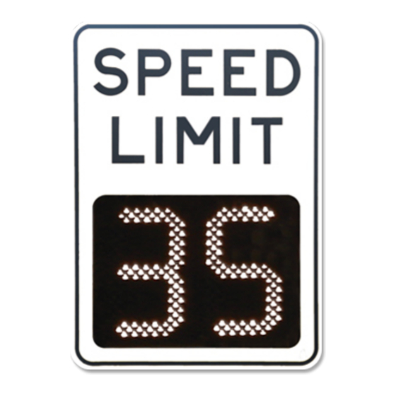
This ensures that motorists are aware when the speed limit has changed. With a built-in strobe and flashing digits to warn violators, the SafePace 550 is ideal for use anywhere that speed limits vary by time of day or week. -
Page 6: About This Manual
About this Manual About this Manual This manual describes the installation of the SafePace 550 sign, along with an optional solar panel, to the side of a pole. This manual also describes the wiring specifications for AC powered, and combined solar/battery powered configurations. -
Page 7: Using Additional Customer Resources
Provides convenient access to the latest versions of our software applications and utilities. Support Videos Provides access to several videos that can help you get up to speed with your Traffic Logix product. Product Documentation Provides access to the most recent versions of our product documentation. -
Page 8: Installing The Safepace 550
Chapter 2 NSTALLING THE There are several methods and hardware options available for the installation of the SafePace 550 sign. It can be mounted with either a pole bracket or a universal sign bracket. SafePace® 550 Installation Manual p. 8... -
Page 9: Selecting A Site For The Sign
Selecting a Site for the Sign Selecting a Site for the Sign The site you select for the sign may vary with the application in which the SafePace 550 radar sign is being used. However, you should generally adhere to the following guidelines: Choose a location where the line of sight from the radar sign to the vehicle will be uninterrupted. -
Page 10: Choosing A Position For The Sign
Choosing a Position for the Sign Similar to other road signs, the SafePace 550 radar sign should be installed near the closest lane of traffic, although off the actual road. The recommended height of the lower edge of the radar speed sign is approximately 7 feet above the surface of the road. -
Page 11: Mounting The Sign
» Using the Standard Pole Banding Mounting The SafePace 550 sign comes with a Standard Pole Banding Mounting system. As this is a standard type of mounting it requires no special knowledge to easily install the sign. The banding straps included are long enough for use with a 5-inch pole. If you want to use a larger pole, you will need to obtain longer banding straps. -
Page 12: Using The Universal Mounting Bracket System (Optional)
Using the Universal Mounting Bracket System (Optional) The SafePace 550 sign comes with an optional Universal Mounting Bracket System that allows you to quickly and easily mount the sign to virtually any type of pole or surface in a secure manner. - Page 13 Using the Universal Mounting Bracket System (Optional) Figure 7: Backside of sign bracket attached. Installing the Pole Bracket The Pole Bracket can be secured to any type of standard pole or Telespar type pole by a choice of banding straps, lag screws, or bolts and nuts. We recommend that you install the bracket on a 2-inch Telespar pole.
- Page 14 Using the Universal Mounting Bracket System (Optional) It is very important that the head of the bolt be placed on the Telespar pole (see Figure 10: below) and that the nuts be placed on the inside part of the bracket (see Figure 11: below). Figure 10: Pole bracket with bolts on the Telespar pole Figure 11: Pole bracket with nuts placed on the inside of the sign bracket To install the Pole Bracket using the supplied banding straps:...
- Page 15 Position the pole bracket and secure it to the surface with the screws. Mounting and Dismounting the Sign Once you have installed the mounting brackets, you can easily mount the SafePace 550 sign by sliding it down onto the Pole Bracket. Once mounted, you should lock the sign into place.
- Page 16 Using the Universal Mounting Bracket System (Optional) Use the supplied key to lock the sign in place. To dismount the sign: Unlock the sign. Slide the sign up and off of the Pole Bracket. SafePace® 550 Installation Manual p. 16...
-
Page 17: Power Options For Your Sign
Chapter 3 OWER PTIONS FOR YOUR The SafePace 550 sign is offered in several powering models. Depending on what model you have purchased, powering the sign will vary. The available power options are as follows: AC powered » Solar powered (uses 3 4-cell Lithium batteries for backup) »... -
Page 18: Ac Power
AC Power AC Power The SafePace 550 sign is equipped to accept 100-240 volts of AC power. For these signs (standard model), the regulated power supply comes already pre-wired, and your sign is ready to operate once it is mounted and wired to the incoming power supply. -
Page 19: Solar Power
Solar Power Solar Power The Solar powered model of the SafePace 550 sign includes a solar panel and mounting bracket, one or more 4-cell lithium batteries, and a solar charger. The solar panel powers the sign when exposed to sunlight while at the same time charging the batteries to provide a power backup for night-time and cloudy day use. -
Page 20: Wiring The Solar Panel To The Sign
Wiring the Solar Panel to the Sign The solar panel should be angled 15 degrees above the latitude of the installation site. For example, if the latitude of the installation site is 45 degrees then the solar panel should be installed at an angle of 60 degrees, as shown. - Page 21 Wiring the Solar Panel to the Sign To wire the solar panel to the sign: Insert the connectors from the sign into the corresponding connectors from the solar panel as shown below. Slide the connectors together until you hear a click and you can no longer slide them apart easily. Once connected the cables should look like the following: Open the sign then connect the battery connectors for the solar charger as shown in the following image.
-
Page 22: Battery Power
The Lithium batteries supplied with the SafePace 550 sign are stable and safe when handled and used properly. Do not bend the batteries or attempt to puncture them with sharp objects as this could cause a fire and/or explosion. - Page 23 Battery Power To install the battery in the battery bracket: Pull on the plunger pins on either end of the upper bracket and flip open the bracket door. Gently insert the battery into the lower bracket and lay the battery flat against the enclosure. Gently close the battery bracket door and make sure the plunger pin locks into place.
-
Page 24: Sign Operation And Maintenance
Chapter 4 PERATION AND AINTENANCE SafePace® 550 Installation Manual p. 24... -
Page 25: Opening And Closing The Sign Latches
Opening and Closing the Sign Latches Every Traffic Logix sign comes with two or three over-center draw type latches. These latches help to protect the internal components of the sign from vandalism as well as water infiltration. As shown in the following illustration the important components of these latches are the lever, the blade and the catch. - Page 26 Opening and Closing the Sign Latches Lower the lever until flat against the surface of the enclosure as shown in the following image. Use the supplied key to lock the latch. SafePace® 550 Installation Manual p. 26...
-
Page 27: Operating Your Sign
You can get the latest version of all manuals at: http://www.trafficlogix.com/customerarea/customerdownloads. Turning the Sign On and Off There is no ON/OFF switch supplied with the SafePace 550 sign. The sign immediately powers on once the power source is connected. To turn the sign off: Do one of the following: On battery powered models, simply disconnect the battery connectors. -
Page 28: Replacing Key Components
Replacing Key Components Replacing Key Components The SafePace 550 sign is comprised of the following key electronic components (and respective quantities): Controller Card (1) » Radar Head (1) » BlueFin Bluetooth Controller (1) » DigiFin LED Digit Segment Controller (1) »... -
Page 29: Warranty
Terms of Use and any Applicable Safety Laws. Buyer agrees that there shall be no coverage or benefits of any kind under this limited warranty if it is determined by Traffic Logix that the Product was not installed or used in accordance with the Conditional Terms of Use or Applicable Safety Laws, or if the Product has been SafePace®... - Page 30 Warranty altered in any way by anyone other than Traffic Logix, or if the Product has been subject to any misuse or accident. In addition, Buyer assumes and agrees to indemnify Traffic Logix for all risk, liability or expense that results from any installation or use of the Product that is not in accordance with the Conditional Terms of Use or any Applicable Safety Laws.
Need help?
Do you have a question about the SAFEPACE 550 and is the answer not in the manual?
Questions and answers