Table of Contents
Advertisement
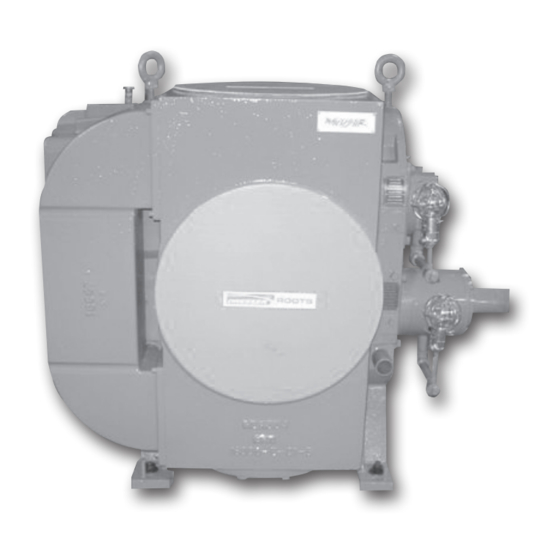
DVJ WHISPAIR
Dry Exhauster
Installation, Operation & Maintenance
Contents
Information Summary ...........................................................1
Warranty and Limitation of Liability ........................................2
Operating Characteristics .....................................................3
Operating Limitations ............................................................4
Installation ...................................................................... 5-10
Do These Things To Get The Most From Your ROOTS
o Check shipment for damage. If found, file claim with
carrier and notify nearest Sales Office. See List on last
page.
o Unpack shipment carefully and check contents against
packing List. Notify Sales Office if a shortage appears.
o Store in a clean, dry location until ready for installation.
Lift by methods discussed under installation to avoid
straining or distorting the equipment. Keep covers on
all openings. Protect against weather and corrosion if
outdoor storage is necessary.
o Read LIMITATIONS and INSTALLATION sections in this
manual and complete the installation.
o Provide for adequate safeguards against accidents to
persons working on or near the equipment during both
installation and operation. SEE SAFETY PRECAUTIONS.
o Install all equipment correctly. Foundation design must be
adequate and piping carefully done. Use recommended
accessories for operating protection.
ILRB-3006 0810
The original ROOTS blower still leads the way
™
Lubrication ................................................................... 10-11
Operation ..................................................................... 12-13
Troubleshooting ..................................................................14
Maintenance/Replacements ......................................... 16-22
Sectional Drawings ....................................................... 23-26
Blower
™
o Make sure both driving and driven equipment is correctly
lubricated before start-up. See LUBRICATION.
o Read starting checkpoints under OPERATION. Run
equipment briefly to check for installation errors and make
corrections. Follow with a trial run under normal operating
conditions.
o In event of trouble during installation or operation, do
not attempt repairs of Roots furnished equipment. Notify
nearest Sales Office giving all nameplate information plus
an outline of operating conditions and a description of the
trouble.
o Unauthorized attempts at equipment repair may void
Manufacturer's warranty. Units out of warranty may be
repaired or adjusted by the owner. It is recommended
that such work be limited to the operations described
this manual, using Factory Parts. Good inspection and
maintenance practices should reduce the need for
repairs.
.
™
Advertisement
Table of Contents

Related Manuals for Dresser Roots DVJ WHISPAIR


Summary of Contents for Dresser Roots DVJ WHISPAIR
-
Page 1: Table Of Contents
The original ROOTS blower still leads the way ™ DVJ WHISPAIR ™ Dry Exhauster Installation, Operation & Maintenance Contents Information Summary ............1 Lubrication ..............10-11 Warranty and Limitation of Liability ........2 Operation ..............12-13 Operating Characteristics .............3 Troubleshooting ..............14 Operating Limitations ............4 Maintenance/Replacements ......... -
Page 2: Operating Characteristics
Operating Characteristics DVJ WHISPAIR dry vacuum exhausters are covered in this discharge air returned to the pockets in RAS WHISPAIR ™ manual. In size they range from 10 inches through 20 inches design. The cooling effect allows blower operation at higher gear diameter. -
Page 3: Operating Limitations
27.0 1800 1021 27.0 1800 1220 27.0 1500 1222 24.0 1500 1428 22.5 1300 1431* 22.0 1300 1639 18.5 1130 1643 16.5 1130 1833 24.0 1000 1838 21.5 1000 *Requires GE drive arrangement above 20" Hg. 4 | Dresser Roots... -
Page 4: Installation
Table 2 - DVJ Clearances Impeller Ends Impeller Strips To Cylinder Impeller Lobes Max. Blower Temp Rise Size -°F Thrust Gear End Inlet Center Disch. Fronts Backs Ends Min. 1016 .010/.012 .023/.027 ---- ---- .014/.016 .010/.012 .014/.016 .020/.024 .010/.014 275° 1021 .010/.012 .032/.036... - Page 5 Blowers should be leveled as level as possible but left with a rough surface. from drive shaft and pipe flanges. Machined baseplates have pads running in both length and width directions. On Spring-type vibration isolating mounting are not recommended 6 | Dresser Roots...
- Page 6 soleplates, the machined top surfaces are used for leveling. deflections can occur during shipping and installation. A Scrape pads or surfaces clean, and remove burrs on high close coupling alignment should be obtained during leveling, points with a flat file. so that only small final adjustments will need to be made after grouting.
- Page 7 40,000 12.3 the blower sufficiently to permit belts to be laid in their sheave grooves easily. Do not pry or roll them into place. Before doing this, inspect all grooves for burrs, rough spots or oil 8 | Dresser Roots...
- Page 8 Figure 3 – Installation with Suggested Locations for Available Accessories (DVJ) Figure 4 – Installation with Suggested Locations for Available Accessories (RGS-DVJ) DVJ WHISPAIR Dry Exhauster | 9 ™...
-
Page 9: Lubrication
Oil should be changed after the first 100 hours of operation. atmospheric pressure. After initial oil change, normal oil change periods under these conditions may be considered as 2000 operating hours. 10 | Dresser Roots... - Page 10 Table 4 - Oil Sump Capacities Blower Gearbox - gallons (liters) Opposite Gear End Bearings - fluid oz. (liters) Frame Vertical Horizontal Driven Shaft Drive Shaft Coupled Drive Shaft Belted Size 1000 ¾ (2.8) 2 (7.6) 4 (.12) 4 (.12) 12 (.36) 1200 1½...
-
Page 11: Operation
Do not reach into any opening in the and the suction area of vacuum relief valves. blower while it is operating, or while subject to • Avoid extended exposure in close proximity to accidental starting. Cover external moving parts machinery which exceeds safe noise levels. with adequate guards. 12 | Dresser Roots... - Page 12 • Use proper care and good procedures in handling, • Do not use air blowers on explosive or hazardous lifting, installing, operating and maintaining the gases. equipment. • Other potential hazards to safety may also be • Casing pressure must not exceed 25 PSI (172 kPa) associated with operation of this equipment. All gauge. Do not pressurize vented cavities from an personnel working in or passing through the area external source, nor restrict the vents. should be warned by signs and trained to exercise adequate general safety precautions.
-
Page 13: Troubleshooting
Remove build-up to restore original clearances and impeller balance. Driver or blower loose Tighten mounting bolts securely. Piping resonances Determine whether standing wave pressure pulsations are present in the piping. Refer to Sales Office. 14 | Dresser Roots... - Page 14 Rotary Lobe Blower Vibrations Rotor unbalance and bent shaft will generate vibrations at 1XRPM. The general vibration severity charts derived from Rathbone Blower/driver coupling misalignment will generate vibration severity charts provide guidelines for machines vibrations at 1XRPM and 2XRPM. basically having mass unbalance-turbomachinery, electric motors, etc.
-
Page 15: Maintenance/Replacements
Table 9. Refer to the drawing applying to the type unit Apply NEVERSEEZ paste on the gear locking device being repaired while reading the instructions. screw threads, under the screw heads, on the tapered rings, on the collar tapers, and on the gear hub outside diameters. 16 | Dresser Roots... - Page 16 Slide each tapered ring collar and the web clearance Figure 7 - Taper Gear Remover holes and screw them loosely into the opposite collar. Do not tighten screws at this time. DEGREASE GEAR HUB BORE AND SHAFT. THE GEARFIT MUST BE FREE OF ANY LUBRICANT. Install two 12"...
- Page 17 THE GEAR SHOULD MOVE .065 to .075". Loosen up the installation capscrews and remove the gear installation tooling. Install gear locknut and tighten nut with a spanner wrench. 18 | Dresser Roots...
- Page 18 to its impeller, and set the impeller “front” clearance so Seal Installation Guide that it is two-thirds of the total clearance found in Step 3. Make sure that any backlash in the gears is taken up in the direction of rotation with the lower gear driving. Tighten all screws as in Step 7.
- Page 19 Set the drive end clearance first, after installing and tightening drive shaft end cover (58) if used. With feeler gauges, carefully measure the spaces between the drive end bearing carrier flanges and the Figure 14 20 | Dresser Roots...
- Page 20 18" RK18ACP00 LOCKWASHER-BRG. 20" RK20ACP00 SEAL-HDPLT BEARINGS BEARINGS* WHEN ORDERING CONTACT: O-RING Dresser Roots GASKETS 900 West Mount Street 1 Set GEAR SCREWS** Connersville, IN 47331-1675 *V-Belt kits only **12" kits and above Phone: 765-827-9200 Rapifax: 765-827-9309 DVJ WHISPAIR Dry Exhauster | 21...
- Page 21 Vertical style units use one item 110 and one item 111. Not required on horizontal units. Inboard bearing item 60 is a double row spherical type on current production units, and the cylindrical roller bearing on older units will be replaced with the new spherical roller bearing. 22 | Dresser Roots...
-
Page 22: Sectional Drawings
Figure 15 - Assembly of 10" thru 12" DVJ-V V-Belt Drive Splash Lube... - Page 23 Figure 16 - Sectional Assembly of 10" thru 14" DVJ-V Blowers...
- Page 24 Figure 17 - Sectional Assembly of 16 - 20 DVJ Common Lube...
- Page 25 Figure 18 - Sectional Assembly of 1016 DVJ-V Units...
Need help?
Do you have a question about the Roots DVJ WHISPAIR and is the answer not in the manual?
Questions and answers