
Summary of Contents for Johnson & Johnson Surgical Vision Veritas
- Page 1 OPERATOR MANUAL Z370584 Rev. D, 09/2020 © Johnson & Johnson Surgical Vision, Inc. 2020 Software Release: 8.000...
- Page 2 This page was intentionally left blank. Z370584 Rev. D...
- Page 3 ™ This manual contains information for the VERITAS Vision System. The information contained in this document is the confidential and proprietary property of Johnson & Johnson Surgical Vision, Inc. No part of this publication may be reproduced or transmitted in any form or by any means, electronic or mechanical, including photocopying, recording, or any information storage and retrieval system, without permission in writing from Johnson &...
- Page 4 This page was intentionally left blank. Z370584 Rev. D...
-
Page 5: Table Of Contents
VERITAS Vision System Components ........1-9... - Page 6 Tubing Packs ........... . . 3-4 VERITAS Advanced Fluidics Tubing Pack ....... . . 3-5 VERITAS Advanced Infusion Tubing Pack.
- Page 7 VERITAS Foot Pedal Setup ........
- Page 8 VERITAS Remote Control Pairing........7-9 Wireless VERITAS Remote Control Test ........7-10 System Versions .
- Page 9 Battery Replacement – VERITAS Foot Pedal and Advanced Linear Pedal . . . 10-3 Battery Replacement – VERITAS Remote Control ..... . 10-4 Charging Options for Wireless Foot Pedals .
- Page 10 Bluetooth Characteristics .........12-17 Phacoemulsification Specifications .
-
Page 11: Introduction
The VERITAS Vision System is a premium cataract system with the intended use of phaco fragmentation and removal of the crystalline lens during cataract surgery. The VERITAS Vision System features technological advancements in fluidics management and ergonomic improvements for the console, foot pedal, handpiece, and remote control. -
Page 12: Introduction
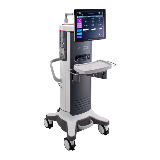
Introduction Figure 1-1 — VERITAS Vision System (front) 1. Programmable IV Pole 3. Front Panel Connections (see Figure 4-1) 2. Tubing Pack inserted 4. Foot Loop for system repositioning Introduction Z370584 Rev. D... -
Page 13: Document Conventions
Introduction The VERITAS Vision System consists of the following components: 1. Programmable IV Pole – supports hanging bottle or bag for fluid management 2. Tubing Pack – disposable to realize the fluid handling during irrigation / aspiration (see separate Instructions for Use) 3. -
Page 14: Intended Use / Indications
NOTE: Provides background information to clarify a particular step or procedure. Intended Use / Indications The VERITAS Vision System is a modular ophthalmic microsurgical system that facilitates anterior segment (cataract) surgery. The modular design allows the users to configure the system to meet their surgical requirements. -
Page 15: Clinical Benefits
Introduction Clinical Benefits Clinical benefits of the VERITAS Vision System include the following: • Rapid visual rehabilitation • Early resumption of daily activities • Minimal ocular inflammation • Minimal postoperative astigmatism • Reduced potential for ocular complications Performance Characteristics •... -
Page 16: Device Description
The solid wheel base and locking wheels make the console stable and smooth rolling. An adjustable height Mayo tray accommodates the handpieces and tubing. The VERITAS Remote Control uses standard commercially available AA batteries for easy replacement. The foot pedal can be stored on a hanging hook when not in use. - Page 17 The up and down arrows on the touchscreen or the wireless VERITAS Remote Control raises or lowers the irrigation source that contains the bottled balanced salt solution, while maintaining the sterility within the operating field. A separate up and down switch allows IV pole adjustment from the side of the system.
-
Page 18: Veritas Vision System Operating Modes
30 cm to the programmed IV Pole height due to pressurizing the irrigation source. VERITAS Vision System Operating Modes The design of the system provides all the operating modes and surgical capabilities that the anterior segment surgeon or the cataract surgeon requires. These capabilities include: Phacoemulsification (Phaco) You use the phacoemulsification mode to break up (emulsify) the nucleus of the lens. -
Page 19: Fusion Fluidics System
The foot pedal controls the various operating modes of the instrument. You can program the foot pedal settings through the user interface. You can use either the VERITAS Foot Pedal, Single Linear Foot Pedal, Advanced Control Pedal, or the Advanced Linear Pedal with the system. -
Page 20: Accessories
ELLIPS FX Handpiece The ELLIPS FX phaco handpiece is available for use with the VERITAS Vision System. The ELLIPS FX handpiece provides both longitudinal and transversal movement. You can use the handpiece with a straight tip or a curved tip. - Page 21 Introduction The WHITESTAR ICE Technology was the next advance in micropulse phacoemulsification technology. This technology combined modulated ultrasonic power (pulse shaping) with vacuum control through the use of the Chamber Stabilization Environment (CASE). This pulse shaping technology modified the standard “square” wave pulse, by increasing the amplitude of the first millisecond of the on time “kick”.
- Page 22 This page was intentionally left blank. Z370584 Rev. D 1-12...
-
Page 23: Warnings, Cautions, And Other Residual Risks
2 — Warnings, Cautions, and Other Residual Risks • “Cautions” on page 2-1 • “Warnings” on page 2-3 • “Residual Risks” on page 2-8 • “Regulatory Symbol Definitions” on page 2-8 • “Regulatory Compliance Statements” on page 2-10 • “System Disposal” on page 2-11 •... - Page 24 Warnings, Cautions, and Other Residual Risks • Do not operate the system in a condensing environment (over 95% relative humidity). Take care to protect the instrument from fluid sprays or fluid buildup. To protect the patient from contaminated fluids or handpieces, use only: ...
-
Page 25: Warnings
Only a trained licensed physician can use this device. ™ • Do not modify the VERITAS Vision System. • The system comes equipped with a 3-prong power plug which you must plug into an outlet with a ground receptacle. - Page 26 • Place monitoring electrodes or other types of equipment as far from those of the VERITAS Vision System as possible. JJSV recommends high current limiting devices for the protection of such systems. Do not use needle monitoring electrodes.
- Page 27 Warnings, Cautions, and Other Residual Risks • This unit complies with all Electromagnetic Interference (EMI) standards and requirements. It is possible that interference provided by the operation of the HIGH FREQUENCY (HF) SURGICAL EQUIPMENT can adversely influence the operation of other electronic equipment.
- Page 28 Do not have the handpiece tip in the eye of the patient when you prime and tune the handpiece. • Do not use non-JJSV approved products with the VERITAS Vision System, as this can affect overall system performance. JJSV cannot be responsible for system surgical performance if you use these products in surgery.
- Page 29 Do not replace the foot pedal battery when the pedal is attached to a power source. • The VERITAS Vision System may be interfered with by other equipment, even if that other equipment complies with regulatory emission requirements such as the International Special Committee on Radio Interference (CISPR).
-
Page 30: Residual Risks
Warnings, Cautions, and Other Residual Risks Residual Risks The final Relative Residual Risk Level Rating for all VERITAS Vision System items was determined to be either Low or Medium. Risk has been mitigated As Far As Possible (AFAP), and is outweighed by the device's benefits. - Page 31 Warnings, Cautions, and Other Residual Risks Symbol Definition Reference Standard Catalogue number ISO 15223-1:2016 Medical devices – Symbols to be used with medical device labels, labeling and information to be supplied – Part 1: General requirements Symbol reference # 5.1.6 Serial number ISO 15223-1:2016 Medical devices –...
-
Page 32: Regulatory Compliance Statements
Warnings, Cautions, and Other Residual Risks Symbol Definition Reference Standard Humidity limitation ISO 15223-1:2016 Medical devices – Symbols to be used with medical device labels, labeling and information to be supplied – Part 1: General requirements Symbol reference #5.3.8 Packaging unit ISO 7000 Graphical symbols for use on equipment –... -
Page 33: Industry Canada (Ic) Notice Of Compliance
System Disposal WEEE This symbol is located on the VERITAS Vision System and indicates that the equipment consists of electronic assemblies and other components that may be subject to Directive 2012/19/EU, of the European Parliament, which advises that Electrical and Electronic Equipment (EEE) must not be disposed of as normal domestic refuse. -
Page 34: Registration, Evaluation, Authorization And Restriction Of Chemicals (Eu Reach)
(ACP) Advanced Linear Pedal (ALP) VERITAS Foot Pedal Format of this table is in compliance with SJ/T11364-2006. O: Indicates that this toxic/hazardous substance contained in all of the homogeneous materials for this part is below the limit requirement in GB/T26572. -
Page 35: Packaging Information
Warnings, Cautions, and Other Residual Risks Packaging Information The packaging for the VERITAS Vision System weights 187 pounds (85kg) and consists of wood and foam. Serious Incident Reporting Report all serious incidents to JJSV and the national competent authority. Incidents should be reported to JJSV via email based on region as shown below. - Page 36 This page was intentionally left blank. Z370584 Rev. D 2-14...
-
Page 37: System Components
Your JJSV representative will contact you to schedule both the installation and the in-service training when you receive your new VERITAS Vision System. We suggest that you leave the VERITAS Vision System in the original packaging. Store the package in a cool, dry environment until the JJSV installation personnel arrive to assemble, install, and test your equipment. -
Page 38: Veritas Vision System Components
System Components Figure 3-1 — VERITAS Vision System (front) 1. Programmable IV Pole 6. On/Off button 2. Touchscreen monitor 7. VERITAS Remote Control storage 3. Tubing Pack inserted 8. Foot Pedal stored on J-Hook 4. Front Panel Connections (see Figure 4-1) 9. - Page 39 System Components Figure 3-2 — VERITAS Vision System (back) 1. Power Cord Wrap – Allows for wrapping 3. Storage Compartment – Allows for storage of and storage of the console power cord miscellaneous accessories and foot pedal cable 2. Rear Panel Connections (see...
-
Page 40: Tubing Packs
Each surgical procedure requires a disposable tubing pack. The FUSION Dual Pump Tubing Pack, VERITAS Advanced Infusion Tubing Pack, and the VERITAS Advanced Fluidics Tubing Pack work with both the peristaltic pump and the Venturi pump. All the supported packs are dual pump packs, so you can select either pump while you are in a surgical case. -
Page 41: Veritas Advanced Fluidics Tubing Pack
FUSION Dual Pump Tubing Pack with smaller bore aspiration tubing. It also features a male irrigation luer lock fitting to help secure the connection to a handpiece possessing the mating feature. Figure 3-3 — VERITAS Advanced Fluidics Tubing Pack 1. Spike (To Irrigation Bottle) 4. I/A Tubing Set (To Handpiece) 2. -
Page 42: Veritas Advanced Infusion Tubing Pack
4. I/A Tubing Set (To Handpiece) WARNING! Bottles are the only irrigation source specified for use with the VERITAS Advanced Infusion Tubing Pack. Using the VERITAS Advanced Infusion Tubing Pack with a bag as the irrigation source could result in a lower irrigation pressure than what is reported by the system. -
Page 43: Fusion Dual Pump Tubing Pack
System Components FUSION Dual Pump Tubing Pack The FUSION Dual Pump (DP) Tubing Pack (OPO73) (Figure 3-5) includes support for the flow based peristaltic aspiration pump and the vacuum based Venturi aspiration pump. Figure 3-5 — FUSION Dual Pump Tubing Pack 1. -
Page 44: Foot Pedal
If the foot pedal is not activated four to six minutes after the system is shut down, the wireless foot pedals go into a power-save mode. • To wake-up the VERITAS Foot Pedal after you start up the system, depress and release the treadle or any of the buttons. •... - Page 45 System Components Figure 3-6 — VERITAS Foot Pedal 1. Handle 4. Treadle 7. Wireless Indicator 2. Left/Right Top Switches 5. Heel Rest 8. Battery Indicator 3. Left/Right Side Switches 6. Cable Connector Figure 3-7 — Single Linear Foot Pedal 1. Handle 4.
- Page 46 System Components Figure 3-8 — Advanced Control Pedal 1. Left yaw 4. Adjustable Heel Stop 7. Right yaw 10. Wireless Indicator 2. Wake-up button 5. Right heel switch 8. Handle 11. Battery Indicator 3. Left heel switch 6. Lights 9. Treadle Figure 3-9 —...
-
Page 47: Removing The Handle From The Advanced Linear Pedal
System Components Removing the Handle from the Advanced Linear Pedal 1. To remove the handle, press the clips on either side of the handle. Figure 3-10 — Foot Pedal Handle Diagram 2. Remove the cover of the handle. 3. Remove the screws and store the screws and handle in a safe place. NOTE: Do not lose the handle as it cannot be replaced. -
Page 48: Foot Pedal Operation
System Components Foot Pedal Operation The foot pedal has three active “pitch” ranges, which are referred to as positions 1, 2 and 3 (FP1, FP2, FP3). Position 0 is the off position, and position 3 is the fully pressed position. The ranges are shown below. -
Page 49: Foot Pedal Storage
System Components Foot Pedal Storage The Advanced Linear Pedal and VERITAS Foot Pedal can be stored on the system on the J- Hook as shown in Figure 3-1, Figure 3-2, and Figure 3-12 below. Figure 3-12 — Foot Pedal Storage Z370584 Rev. -
Page 50: Veritas Heel Insert (Optional)
3-13) is an optional accessory for use with the VERITAS Foot Pedal. The VERITAS Heel Insert shifts the foot forward on the treadle, which may be more comfortable for some users. The VERITAS Heel Insert attaches to the VERITAS Foot Pedal by magnetic attraction. -
Page 51: Programmable Iv Pole
The wireless VERITAS Remote Control keypad can be used to move between the surgical modes and submodes. Adjustments to the surgical mode and submode settings can be made with the VERITAS Remote Control. The buttons on the remote keypad work the same as the controls on the system touchscreen monitor (see Figure 3-14 below). - Page 52 After you turn the system on, press any button to activate the VERITAS Remote Control. NOTE: After four to six minutes of idle time, the VERITAS Remote Control goes into a power- save mode. To turn the VERITAS Remote Control on, press any button.
-
Page 53: Veritas Remote Control Storage
System Components VERITAS Remote Control Storage The VERITAS Remote Control can be stored on the system as shown in Figure 3-1, Figure 3-2, Figure 3-15 below. Figure 3-15 — VERITAS Remote Control Module Storage Surgical Media Center (SMC) (Optional) The optional Surgical Media Center (SMC) is used to record the surgery and the instrument settings to be viewed at a later date and time. - Page 54 This page was intentionally left blank. Z370584 Rev. D 3-18...
-
Page 55: Surgery Start Up
“System Shutdown” on page 4-26 VERITAS Vision System Setup ™ This is a general overview of the steps to prepare the VERITAS Vision System for surgery: 1. Attach the power cord to the power cord connector on the rear panel of the console (see... -
Page 56: Front And Rear Panel Connections
Front and Rear Panel Connections This section shows the front and rear panel connections. See Figure 3-1 Figure 3-2 locations on the VERITAS Vision System. Figure 4-1 — Front Panel Connections 1. Vitrectomy handpiece 2. Diathermy handpiece 3. Phaco handpiece Front and Rear Panel Connections Z370584 Rev. - Page 57 Surgery Start Up Figure 4-2 — Rear Panel Connections 1. USB port 5. Power switch 2. Communication port 6. Fuse holder 3. Foot pedal connector 7. Power cord connector 4. Potential equalizer CAUTION! Securely attach plugs, handpiece cables, and other connectors. Z370584 Rev.
-
Page 58: Iv Pole Setup
Handpiece Setup This section presents information about setting up the handpieces. • “Phacoemulsification Handpiece Setup – VERITAS Swivel” on page 4-5 • “Phacoemulsification Handpiece Setup – WHITESTAR and ELLIPS FX” on page 4-7 • “Irrigation/Aspiration Handpiece Setup” on page 4-9 •... -
Page 59: Phacoemulsification Handpiece Setup - Veritas Swivel
Surgery Start Up Phacoemulsification Handpiece Setup – VERITAS Swivel WARNING! Sterility assurance is the responsibility of the user. You must sterilize all non-sterile accessories prior to use. WARNING! Prior to using any invasive portions of the handpiece assembly, examine under the microscope for any obvious damage, oxidation, or the presence of foreign material. - Page 60 Surgery Start Up Figure 4-4 — VERITAS Swivel Handpiece NOTE: You can use the VERITAS Swivel handpiece with WHITESTAR Technology phaco settings. 5. Insert the male luer end of the irrigation tubing into the phaco handpiece. 6. Attach the female luer fitting end of the aspiration tubing to the phaco handpiece.
-
Page 61: Phacoemulsification Handpiece Setup - Whitestar And Ellips Fx
2. Irrigation Sleeve 3. Phaco Tip 4. Handpiece 4. Attach the connector end of the handpiece to the phaco receptacle on the front of the VERITAS Vision System (see Figure 3-1 Figure 4-1). 5. Ensure there is no moisture on the connectors prior to attaching. Moisture prevents the handpiece from operating properly. - Page 62 Surgery Start Up Figure 4-7 — ELLIPS FX Handpiece ™ ™ NOTE: You can use the ELLIPS FX handpiece with WHITESTAR Technology phaco settings. 6. Insert the male luer end of the irrigation tubing into the phaco handpiece. 7. Attach the female luer fitting end of the aspiration tubing to the phaco handpiece. NOTE: To protect the patient from contamination, use only: sterile tubing sets sterile balanced salt solution...
-
Page 63: Irrigation/Aspiration Handpiece Setup
Surgery Start Up Irrigation/Aspiration Handpiece Setup Assemble the SOLO Irrigation/Aspiration (I/A) handpiece by attaching the irrigation sleeve. ™ ™ NOTE: The test chamber is provided in the FUSION Tubing Pack. The LAMINAR Flow 20 gauge irrigation sleeves can also be used and are available with the OPOS20L or any 20 gauge LAMINAR phaco tip. -
Page 64: Vitrectomy Cutter Setup
Surgery Start Up Vitrectomy Cutter Setup If you need to use vitrectomy during surgery: 1. Attach the vitrectomy cutter as shown below. Vitrectomy requires the following components: I/A Tubing (from tubing pack) Vitrectomy cutter Vitrectomy irrigation sleeve, or a 23 Gauge Limbal Infusion tip, if desired. 2. - Page 65 Surgery Start Up Figure 4-13 — Select Surgeon and Program Screen From the main menu you can: • Select a Surgeon/Program and begin surgery based on the values of that program • Access the Settings screen, where you can edit programs and setup operating parameters •...
-
Page 66: Install The Tubing Pack
4. For VERITAS Advanced Infusion Tubing Pack (VRT-AI) only: The infusion line has a black infusion connector at the free end. Insert the infusion connector into the side panel of the... -
Page 67: Cup Fill
Surgery Start Up Cup Fill To collect the balanced salt solution: 1. Use the test chamber, a medicine cup, or similar container. 2. Tap the Prime/Tune button. Figure 4-15 — Prime/Tune Screen with Cup Fill Controls Highlighted 3. Use the up arrow to cycle through the three available amounts of solution to be dispensed. -
Page 68: Prime/Tune
Surgery Start Up NOTE: Ensure you have filled the tubing with fluid using the Continuous Irrigation feature. If the tubing does not have fluid, the amount dispensed during Cup Fill may not be the amount selected. 4. Tap Start to turn on Cup Fill. 5. - Page 69 Surgery Start Up Figure 4-16 — Prime and Tune Screen The system tracks the successful completion of the prime and tune cycles independently. If the system needs to be tuned again (new tip, failed tune), you only need to select and run the tune.
-
Page 70: Suggestions For Priming The Handpieces
Surgery Start Up Suggestions for Priming the Handpieces Do not lay the handpiece and the empty test chamber down and have the system fill the test chamber. When you lay down the handpiece, this allows air to collect in the test chamber and can produce an error. -
Page 71: Verify Irrigation/Aspiration Balance
Surgery Start Up Verify Irrigation/Aspiration Balance We strongly recommend you verify that you balanced Irrigation/Aspiration properly for your settings used in surgery. Figure 4-17 — Irrigation/Aspiration Balance Procedure To verify irrigation/aspiration balance: 1. In Phaco 1 mode, hold the handpiece at the approximate patient eye level. NOTE: The numbers in the drawing Figure 4-17 correspond to the steps listed. -
Page 72: Priming For Vitrectomy
Surgery Start Up Priming for Vitrectomy Before you perform vitrectomy, we recommend you prime the handpiece to reduce the chance of errors. Each time you select vitrectomy mode, a dialog box asks you to prime the vitrectomy handpiece. If you do not need to prime, tap Bypass. To prime the handpiece: 1. -
Page 73: Selecting And Changing Mode Parameters
Surgery Start Up Selecting and Changing Mode Parameters The design of the system's graphical user interface (GUI) and touchscreen is for ease-of-use, and provides a consistent look and maximum informational display during all operating modes. Your interface with the system requires only three basic steps, which apply to all the selections, settings and operations. -
Page 74: System Check-Out
Surgery Start Up • To change other control panel settings, such as Panel or Linear power and nonzero start, tap the Settings button on the right side of the control panel. A Settings screen opens, and you can make your modifications. Figure 4-20 —... -
Page 75: Phacoemulsification
Surgery Start Up Phacoemulsification Follow these steps to check the system out for phacoemulsification. 1. Attach the tubing to the phaco handpiece. 2. Screw the phaco tip onto the handpiece, use your fingers to engage the screw thread, and then use the tip wrench to tighten the tip. 3. -
Page 76: Vitrectomy
Surgery Start Up CAUTION! If you do not hear a tone when you press the foot pedal and volume adjustment is unsuccessful, the mode is not functioning properly. Refer to Chapter 10, "Error Messages, Troubleshooting, and Diagnostics" Vitrectomy Follow these steps to check the system out for vitrectomy. 1. - Page 77 Figure 4-21 — End Case Screen NOTE: For ease of viewing, the EPT, EFX, UST, and DT times are in a large font size on the End Case screen. The EFX shows only when you attach an ELLIPS FX or VERITAS Swivel handpiece.
-
Page 78: Review Case
Surgery Start Up Review Case Tap Review Case to show a graphical history of the surgery (Figure 4-22). Figure 4-22 — Review Case Screen • Select a shorter time interval to adjust the time line duration and to see greater case details. -
Page 79: End Case
Surgery Start Up • Tap Delete Record to remove a case from the Record database. • Tap Print to File to save the data to a file format. Abbreviated Summary – Provides overall case time, total time per mode and case timers. -
Page 80: System Shutdown
5. Remove the power cord from the power outlet. 6. Wrap the excess power cord neatly around the cord wrap on the back of the console. 7. Use the AC Charging Adapter to charge the VERITAS Foot Pedal, ACP, or ALP Foot Pedal. -
Page 81: Surgeon Settings
5 — Surgeon Settings • “Select Surgeon” on page 5-1 • “Add a New Surgeon” on page 5-2 • “Delete Surgeon” on page 5-3 • “Edit a Surgeon” on page 5-3 • “Edit Surgeon Settings” on page 5-4 • “Foot Pedal Setup” on page 5-6 •... -
Page 82: Add A New Surgeon
Surgeon Settings Add a New Surgeon To create a new surgeon: 1. Tap on Select Surgeon. The keyboard screen opens. 2. Enter the name of the surgeon. 3. Tap Enter to save the new surgeon and then exit the keyboard screen. The new surgeon is now on the list of available surgeons. -
Page 83: Delete Surgeon
Surgeon Settings Delete Surgeon To remove a surgeon name from the list: 1. Select the name of the surgeon. 2. Tap on Select Surgeon. 3. At the confirmation dialog box, select Yes. Edit a Surgeon 1. Select a surgeon from the list. Figure 5-3 —... -
Page 84: Edit Surgeon Settings
Surgeon Settings Figure 5-4 — Edit Surgeon Name Screen 3. Edit the name. 4. Tap Enter. Edit Surgeon Settings To define venting, Tap for Irrigation, and Cont. Irr. Auto-Off setting preferences for the selected surgeon: 1. Select a surgeon from the list. Edit Surgeon Settings Z370584 Rev. - Page 85 Surgeon Settings Figure 5-5 — Select Surgeon 2. Tap the Surgeon Settings option on Select Surgeon. The Surgeon Settings screen appears. Z370584 Rev. D Edit Surgeon Settings...
-
Page 86: Foot Pedal Setup
Linear and Dual Linear. Each type has its own set of switch assignments. The Single Linear Foot Pedal, VERITAS Foot Pedal, and Advanced Linear Pedal are Single Linear type foot pedals. The Advanced Control Pedal is a Dual Linear type foot pedal. The switch assignments are shared among the foot pedals belonging to each foot pedal type. -
Page 87: Single Linear Foot Pedal Setup
Surgeon Settings • “Advanced Control Pedal Setup” on page 5-23 • “Advanced Linear Pedal Setup” on page 5-31 Single Linear Foot Pedal Setup This section presents the following topics for setting up a Single Linear Foot Pedal. • “Vitrectomy Foot Pedal Modes” on page 5-8 •... - Page 88 Surgeon Settings Table 5.1 – Single Linear Foot Pedal Default Settings Parameter Available Settings Default Settings Pitch regions 1–100% P1=5% P2=30% P3=60% Switch position Switch1= * Switch1=Off Switch 2= * Switch 2=Off Right= * Right=Reflux Left= * Left=Off Feedback On, Off *Table 5.3 –...
- Page 89 Surgeon Settings The system initially displays the Summary information on the Foot Pedal Settings screen. Each major surgical mode (Phaco, IA, Vitrectomy, and Diathermy) has individual settings for the foot pedal switches. In addition, both Phaco and Vitrectomy modes have individual settings per submode for the foot pedal switches.
- Page 90 Surgeon Settings Figure 5-9 — Switches Screen – Single Linear Foot Pedal The system displays the standard foot pedal switch assignment screen. The Single Linear Foot Pedal Switches screen allows you to assign or change the action for each of the four switches.
- Page 91 Surgeon Settings Figure 5-10 — Single Linear Foot Pedal Switch Assignment Dialog Box 7. Tap the button that represents your choice of switch setting. Table 5.3 – Single Linear Foot Pedal Switch Assignments Switch Setting Description This switch has no switch assignment. Surgeon Program Up Selects the surgeon program above the current program in the list.
- Page 92 Surgeon Settings Switch Setting Description Bottle Down Lowers the IV pole while the switch is held down. Reflux Activates reflux. Continuous Irrigation Activates or deactivates continuous irrigation. 1-Touch Up Increments CASE mode 1-Touch (Phaco only). 1-Touch Down Decrements CASE mode 1-Touch (Phaco only). Toggle CASE Activates or deactivate CASE mode (Phaco only).
- Page 93 Surgeon Settings Figure 5-11 — Single Linear Foot Pedal Thresholds 4. Check the Feedback checkbox to enable foot pedal feedback. Feedback is a physical and audible click as you move the foot pedal to the next or previous position. 5. Tap Save to retain the settings. Single Linear Foot Pedal Calibration and Testing Follow these steps to calibrate and test your foot pedal.
- Page 94 Surgeon Settings Figure 5-12 — Single Linear Foot Pedal Calibration Screen 3. With your foot off the foot pedal, tap the Phase 1 button. 4. Put your foot on the foot pedal, press and hold the foot pedal all the way down and tap the Phase 2 button.
-
Page 95: Veritas Foot Pedal Setup
9. To test the foot pedal before calibration, tap the Test button. The Test button is not available during surgery. VERITAS Foot Pedal Setup This section presents the following topics for setting up a VERITAS Foot Pedal. • “VERITAS Foot Pedal Connections” on page 5-16 •... - Page 96 8. Battery Indicator 3. Left/Right Side Switches 6. Cable Connector VERITAS Foot Pedal Connections You can attach the VERITAS Foot Pedal to the system either with a cable or with a wireless ® Bluetooth connection. NOTE: The blue light on the pedal indicates that the wireless connection is active. The amber light indicates that the battery needs to be charged.
- Page 97 Figure 5-15 — VERITAS Foot Pedal Summary Screen 2. Tap the Switches button to change the settings for the switches. The system displays the VERITAS Foot Pedal Edit screen. This screen allows you to assign or change the action for each of the four switches.
- Page 98 Surgeon Settings Figure 5-16 — VERITAS Foot Pedal Switches Screen 3. Select the major mode and then the applicable submode. 4. Tap the button under each switch name to assign or change the action for that switch. The system displays a switch assignment dialog box with the text of the current switch assignment shown in green.
- Page 99 Surgeon Settings Figure 5-17 — VERITAS Foot Pedal Switch Assignment Dialog Box 6. Tap the button that represents your choice of switch setting. Table 5.4 – VERITAS Foot Pedal Switch Assignments Switch Setting Description This switch has no switch assignment.
- Page 100 8. Tap the Save button to retain the switch assignments. 9. Tap Exit to close the Foot Pedal Set Up screen. VERITAS Foot Pedal Threshold Configuration Follow the steps below to configure the thresholds for the foot pedal. NOTE: In addition to showing the type and status of the foot pedal, the foot pedal icon (shown below) in the top of the screen also allows access to the Foot Pedal Settings screen.
- Page 101 Surgeon Settings Figure 5-18 — VERITAS Foot Pedal Threshold Screen 3. Use the up and down arrows to change the threshold for each of the foot pedal pitch zones. P1 is the first zone, P2 is the second, and P3 is the final zone.
- Page 102 Surgeon Settings VERITAS Foot Pedal Test Figure 5-19 — VERITAS Foot Pedal Test Screen NOTE: In addition to showing the type and status of the foot pedal, the foot pedal icon (shown below) in the top of the screen also allows access to the Foot Pedal Settings screen.
-
Page 103: Advanced Control Pedal Setup
Surgeon Settings 3. Press the foot pedal down fully to position 3. As the foot pedal travels through positions 1 and 2 to position 3, the progress bar shows its current state. When the pedal reaches position 3, the progress bar should be solid green. 4. - Page 104 Surgeon Settings NOTE: See “Charging Options for Wireless Foot Pedals” on page 10-4. Table 5.5 – Advanced Control Pedal Default Settings Parameter Available Settings Default Settings Right/Left Yaw Right Yaw=Reflux Pitch Region 1-100% P1=5% P2=30% P3=60% Yaw Position 5-100% Left=90% Right=90% * Table 5.7 –...
- Page 105 Surgeon Settings 1. On the Surgeons and Programs screen, tap The system initially displays the Summary information on the Foot Pedal Settings screen. Each major surgical mode (Phaco, IA, Vitrectomy, and Diathermy) has individual settings for the foot pedal switches. In addition, both Phaco and Vitrectomy modes have individual settings per submode for the foot pedal switches.
- Page 106 Surgeon Settings Figure 5-22 — Advanced Control Pedal Phaco Switches Screen 3. Select the major mode and then the applicable submode. 4. Tap the button under each switch name to assign or change the action for that switch. The system displays a switch assignment dialog box with the text of the current switch assignment shown in green.
- Page 107 Surgeon Settings Figure 5-23 — Advanced Control Pedal Switch Assignment Dialog Box 6. Tap the button that represents your choice of switch setting. Table 5.7 – Advanced Control Pedal Switch Assignments Switch Setting Description This switch has no switch assignment. Surgeon Program Up Selects the surgeon program above the current program in the list.
- Page 108 Surgeon Settings Switch Setting Description Bottle Down Lowers the IV pole while the switch is held down. Reflux Activates reflux. Continuous Irrigation Activates or deactivates continuous irrigation. 1-Touch Up Increments CASE mode 1-Touch. (Phaco only) 1-Touch Down Decrements CASE mode 1-Touch. (Phaco only) Toggle CASE Activates or deactivates CASE MODE (Phaco only) WhiteStar Increment...
- Page 109 Surgeon Settings Figure 5-24 — Advanced Control Pedal Thresholds 3. Use the right and left arrows to set the threshold for position 1, 2, or 3. The system announces the current value. 4. Use the up and down arrows to set the threshold for the left and right yaw controls. The threshold determines how far the user needs to move the pedal before the switch is activated.
- Page 110 Surgeon Settings Advanced Control Pedal Calibration and Testing Follow the steps below to calibrate and test your foot pedal. NOTE: In addition to the procedure below, you can access the Advanced Control Pedal Summary screen by pressing the foot pedal icon (shown below) near the top of the screen.
-
Page 111: Advanced Linear Pedal Setup
Surgeon Settings Figure 5-26 — Advanced Control Pedal Testing 7. Press the foot pedal down fully to position 3. As the foot pedal travels through positions 1 and 2 to position 3, the progress bar shows its current state. When the pedal reaches the bottom of position 3, the progress bar should be solid green. - Page 112 Surgeon Settings Figure 5-27 — Advanced Linear Pedal 1. Handle 4. Heel rest 7. Battery Indicator 2. Left and Right Top Switches 5. Treadle 3. Left and Right Side Switches 6. Wireless Indicator Advanced Linear Pedal Connections You can attach the Advanced Linear Pedal to the system either with a cable or with a wireless Bluetooth connection.
- Page 113 Surgeon Settings 1. On the Surgeons and Programs screen, tap The system initially displays the Summary information on the Foot Pedal Settings screen. Each major surgical mode (Phaco, IA, Vitrectomy, and Diathermy) has individual settings for the foot pedal switches. In addition, both Phaco and Vitrectomy modes have individual settings per submode for the foot pedal switches.
- Page 114 Surgeon Settings Figure 5-29 — Advanced Linear Pedal Switches Screen 3. Select the major mode and then the applicable submode. 4. Tap the button under each switch to assign or change the action for that switch. The system displays a switch assignment dialog box with the text of the current switch assignment shown in green.
- Page 115 Surgeon Settings Figure 5-30 — Advanced Linear Pedal Switch Assignment Dialog Box 5. Tap the button that represents your choice of switch setting. Table 5.8 – Advanced Linear Pedal Switch Assignments Switch Setting Description This switch has no switch assignment. Surgeon Program Up Selects the surgeon program above the current program in the list.
- Page 116 Surgeon Settings Switch Setting Description Bottle Down Lowers the IV pole while the switch is held down. Reflux Activates reflux. Continuous Irrigation Activates or deactivates continuous irrigation. 1-Touch Up Increments CASE mode 1-Touch (Phaco only). 1-Touch Down Decrements CASE mode 1-Touch (Phaco only). Toggle CASE Activates or deactivates CASE mode, (Phaco only) 6.
- Page 117 Surgeon Settings Figure 5-31 — Advanced Linear Pedal Threshold Screen 3. Use the up and down arrows to change the threshold for each of the foot pedal pitch zones. P1 is the first zone, P2 is the second, and P3 is the final zone. 4.
- Page 118 Surgeon Settings Advanced Linear Pedal Test Figure 5-32 — Advanced Linear Pedal Test Screen NOTE: In addition to the procedure below, you can access the Advanced Linear Pedal Summary screen by pressing the foot pedal icon (shown below) near the top of the screen.
-
Page 119: Set Sound Levels
0–10 The VERITAS System provides two sets of tone options—VERITAS and WHITESTAR SIGNATURE PRO. You can select the tone preference by tapping either VERITAS or WHITESTAR SIGNATURE PRO. Once you select your preferred tone, you can hear a sample of the selected tone by adjusting the volume. - Page 120 Surgeon Settings Follow these steps to set the sound levels for the selected surgeon: 1. On the top panel, select the surgeon. 2. Tap Figure 5-33 — Sound Settings Screen 3. Use the sliders to adjust the volume for: Master Volume ...
-
Page 121: Surgeon - Assign Order
Surgeon Settings Surgeon – Assign Order 1. Select a surgeon. 2. Use to move the surgeon names up or down on the Surgeons and Programs screen. Figure 5-34 — Surgeons and Programs Screen 3. Repeat the steps until the order is to your satisfaction. Z370584 Rev. - Page 122 This page was intentionally left blank. Z370584 Rev. D 5-42...
-
Page 123: Program Settings
6 — Program Settings • “Create a New Program” on page 6-1 • “Delete a Program” on page 6-4 • “Edit a Program Name” on page 6-5 • “Lock a Program” on page 6-5 • “Copy a Surgeon Program” on page 6-5 •... - Page 124 Program Settings Figure 6-1 — Surgeons and Programs Screen 1. On Select Program, tap Create a New Program Z370584 Rev. D...
-
Page 125: Create A New Program
Program Settings Figure 6-2 — Create New Program 2. Enter a program name and tap Enter, or tap Standard Names, select a program name from the list, and tap Enter. Z370584 Rev. D Create a New Program... -
Page 126: Delete A Program
Program Settings Figure 6-3 — Standard Program Names Delete a Program Use Delete Program to remove a surgeon program from the Select Program screen. You cannot delete a program if it is the only program defined for a custom surgeon. You also cannot delete the default 19 gauge, 20 gauge, and 21 gauge programs from the Standard Surgeon. -
Page 127: Edit A Program Name
Program Settings Edit a Program Name 1. Select a program name on the list. 2. Tap 3. Enter a different program name or tap Standard Names and select a new name from the Standard Names list. See “Create a New Program” on page 6-1. -
Page 128: Assign Program Order
Program settings include the following: • Advanced Infusion: If this checkbox is checked (enabled), program settings are customized to use the VERITAS Advanced Infusion Tubing Pack VRT-AI. If Advanced Infusion is disabled, program settings are customized to support tubing packs using ™... - Page 129 Program Settings The default submode names are: • Phaco – Phaco 1, Phaco 2, Phaco 3, Phaco 4 • I/A – IA 1, IA 2, IA 3 • VIT – ICA, IAC • DIA – Diathermy 1, Diathermy 2 Each submode includes: •...
-
Page 130: Phaco
Program Settings Phaco 1. Tap to open the Settings screen. 2. Select a Phaco submode on the left (Figure 6-6). Figure 6-6 — Phaco Settings Screen 3. If desired, tap the submode name at the top of the screen (outlined in red in Figure 6-6) to customize the submode name. -
Page 131: Irrigation And Aspiration (I/A)
Program Settings Irrigation and Aspiration (I/A) to open the Settings screen. 2. Select an Irrigation/Aspiration submode on the left (Figure 6-7). Figure 6-7 — Irrigation/Aspiration Settings 3. If desired, tap the submode name at the top of the screen (outlined in red in Figure 6-7) to customize the submode name. -
Page 132: Vitrectomy (Vit)
Program Settings Vitrectomy (VIT) 1. Tap to open the Settings screen. 2. Select a Vitrectomy submode on the left (Figure 6-8). Figure 6-8 — Vitrectomy Settings Screen 3. If desired, tap the submode name at the top of the screen (outlined in red in Figure 6-8) to customize the submode name. -
Page 133: Diathermy (Dia)
Program Settings 10. Bottle Height Hold: If this checkbox is checked (enabled), the bottle height is held at the Bottle Height value specified in the Vitrectomy submode. 11. Tap Save to save the program. Diathermy (DIA) to open the Settings screen. 2. -
Page 134: Advanced Infusion
Program Settings Advanced Infusion 1. Tap to open the Settings screen. 2. When using the Advanced Infusion Tubing Pack (VRT-AI), the Advanced Infusion checkbox must be checked, as outlined in red in Figure 6-10 below. Figure 6-10 — Advanced Infusion Enabled Program Settings Z370584 Rev. -
Page 135: Default Settings
Program Settings Default Settings Table 6.1 – 19 Gauge Program – Phaco Settings Parameter Available Default Settings Settings Advanced Infusion (Program based) On, Off Function Phaco 1 Phaco 2 Phaco 3 Phaco 4 Submode name Phaco 1 Phaco 2 Phaco 3 Phaco 4 Pump selection Venturi... - Page 136 Program Settings Parameter Available Default Settings Settings Max power Unoccluded (%) Power delivery Continuous Continuous Continuous Continuous ™ WHITESTAR setting (duty On 6/3 (67%) On 8/4 (67%) On VWS (67%) On 4/8 (33%) cycle) Quadrant 1 - 12/6 Quadrant 2 - 10/5 Quadrant 3 - 8/4 Quadrant 4 - 6/3 Occluded mode (%)
- Page 137 Program Settings Table 6.3 – 20 Gauge Program – Phaco Settings Parameter Available Default Settings Settings Advanced Infusion (Program based) On, Off Function Phaco 1 Phaco 2 Phaco 3 Phaco 4 Submode name Phaco 1 Phaco 2 Phaco 3 Phaco 4 Pump selection Venturi Peristaltic...
- Page 138 Program Settings Parameter Available Default Settings Settings Max power Unoccluded (%) Power delivery Continuous Continuous Continuous Continuous WHITESTAR setting (duty cycle) On 6/3 (67%) On 8/4 (67%) On VWS (67%) On 4/8 (20%) Quadrant 1 - 12/6 Quadrant 2 - 10/5 Quadrant 3 - 8/4 Quadrant 4 - 6/3 Occluded mode (%)
- Page 139 Program Settings Table 6.5 – 21 Gauge Program – Phaco Settings Parameter Available Default Settings Settings Advanced Infusion (Program based) On, Off Function Phaco 1 Phaco 2 Phaco 3 Phaco 4 Submode name Phaco 1 Phaco 2 Phaco 3 Phaco 4 Pump selection Venturi Peristaltic...
- Page 140 Program Settings Parameter Available Default Settings Settings Max power Unoccluded (%) Power delivery Continuous Continuous Continuous Continuous WHITESTAR setting (duty cycle) On 6/3 (67%) On 8/4 (67%) On VWS (67%) On 4/8 (33%) Quadrant 1 - 12/6 Quadrant 2 - 10/5 Quadrant 3 - 8/4 Quadrant 4 - 6/3 Occluded mode (%)
-
Page 141: Phaco Power Settings
Program Settings Phaco Power Settings • Continuous • Pulse Mode • Short Pulse • Long Pulse • Low Power Pulse • High Power Pulse • Single Burst (panel only) • Multiple Burst (panel only) • Continuous Burst From the Phaco Settings screen, tap to display the Phaco Power selection. -
Page 142: Continuous Phaco Power
Program Settings Continuous Phaco Power Continuous phaco power delivers continuous, uninterrupted phaco power to the handpiece and requires no pulse rate setting. Pulse Mode Pulse Mode delivers phaco in pulses of 1 to 100 ms when the foot pedal is in position 3. You can set this in a range of 1 to 100 pulses per second (pps). -
Page 143: High Power Pulse Phaco Power
Program Settings High Power Pulse Phaco Power High Power Pulse generates continuous phaco power in foot pedal position 3. When you press the foot pedal, the continuous pulse changes into long pulses and then gradually changes to short pulses. Single Burst Phaco Power (Panel Only) Single Burst delivers a single burst of ultrasonic power of 110 ms duration when you press the foot pedal to position 3. - Page 144 Program Settings Table 6.7 – WHITESTAR Technology Parameter Settings Setting Pulse On Time (ms) Pulse Off Time (ms) Duty Cycle Pulse Rate (pps) 6/12 4/24 6/28 6/24 8/24 6/18 Figure 6-12 — Duty Cycle WHITESTAR Technology Z370584 Rev. D 6-22...
- Page 145 Program Settings When the variable WHITESTAR Technology is used, different duty cycles are applied as the foot pedal moves through the power delivery zone. The zone is divided into four equal size quadrants, and a different duty cycle can be applied in each quadrant (Variable WS). You can also use the sliding adjustments to create custom duty cycles for Variable WS.
- Page 146 Program Settings Figure 6-14 — Duty Cycles for Variable WS WHITESTAR Technology Z370584 Rev. D 6-24...
- Page 147 Program Settings WHITESTAR ICE Technology (Pulse Shaping) The WHITESTAR ICE Technology was the next micro-pulse advance in phacoemulsification technology, which combined modulated ultrasonic power (pulse shaping) with vacuum control through the application of the Chamber Stabilization Environment (CASE). This pulse shaping technology modifies the standard square wave pulse, by increasing the amplitude of the two milliseconds of the on time “kick”, and then setting the remaining part of the on time to the standard power setting.
- Page 148 Program Settings Figure 6-16 — Pulse Shaping Screen There are four settings for WHITESTAR ICE Pulse Shaping: • Low Power Limit • High Power Limit • Percent Kick Low End of Range • Percent Kick High End of Range The Low Power Limit and High Power Limit settings define the range of the applied pulse shaping.
-
Page 149: Fusion Fluidics Phaco
Program Settings FUSION Fluidics Phaco FUSION Fluidics Phaco is an intelligent vacuum monitoring system that regulates the maximum allowable vacuum that follows an occlusion of the phaco tip. When the phaco tip becomes occluded, the vacuum rises. Clearing of the occlusion while the vacuum is at a high-level can cause a post-occlusion surge. -
Page 150: Occlusion Mode Settings
Program Settings Figure 6-18 — Phaco Surgical Screen with Occlusion and CASE On Occlusion Mode Settings With Occlusion Mode, you can set different aspiration rates for occluded aspiration as opposed to unoccluded aspiration. You can set a different vacuum rise time for when the phaco tip occludes without changing the aspiration rate through an unoccluded tip. - Page 151 Program Settings Figure 6-19 — Occlusion Mode Settings Screen 4. Use the up and down arrows to adjust the pump ramp 5. Tap the FUSION button ( 6. On the FUSION screen, use the up and down arrows to adjust the threshold and the Actual Max Vac.
-
Page 152: Occlusion Vacuum Threshold
Program Settings Figure 6-20 — FUSION Settings Screen 7. Tap Finished to close the screen. 8. Tap Save to retain the settings. 9. Tap Exit to close the screen. Occlusion Vacuum Threshold In Occlusion mode phaco, you can set an occlusion threshold value for vacuum. When in Occlusion mode phaco, there is an additional control panel for vacuum. -
Page 153: Occlusion Mode Power Settings
Program Settings Figure 6-21 — Occlusion Aspiration Rate To adjust the occluded aspiration rate in Occlusion mode phaco, tap the up or down arrows to increase or decrease the occluded aspiration rate. 1. Tap The Settings screen opens. 2. Tap the up or down arrows to increase or decrease the occluded aspiration rate. 3. - Page 154 Program Settings Figure 6-22 — Phaco Surgical Screen with Occlusion Mode Power Settings ™ 1. VERITAS Swivel with ELLIPS FX Technology 2. WHITESTAR Technology without Pulse Shaping To adjust the occluded power delivery: NOTE: Nonzero start parameters are the same for unoccluded and occluded settings. When the current value reaches the occlusion threshold then the system uses the occlusion settings.
-
Page 155: Venting An Occlusion
Program Settings Venting an Occlusion As discussed earlier in this chapter, vacuum builds when the aspiration tip is blocked or occluded by tissue or other material. The fluidics system relieves vacuum in the aspiration line when the foot pedal traverses from position 2 to position 1. The fluidics system applies variable venting pressure of Low, Medium, or High to the aspiration line as selected in the surgeon settings to release the material at the aspiration tip when the foot pedal is released to position 0. - Page 156 Program Settings Figure 6-23 — FUSION Settings Screen 3. On the FUSION screen, tap the On button to turn CASE mode on. NOTE: If the Venturi pump option is on, you cannot access the FUSION Fluidics screen. There is no Occlusion mode phaco or CASE mode with Venturi. 4.
-
Page 157: Case One Touch
Program Settings CASE One Touch To simplify the programming of the CASE function, you only need to define the basic CASE parameters once. You can adjust the CASE function quickly and easily from the CASE One Touch settings on the surgical screen. Use these controls to change the CASE functionality for greater efficiency (up arrow) or more control (down arrow) to suit any particular combination of cataract density, surgical technique, or personal preference. - Page 158 This page was intentionally left blank. Z370584 Rev. D 6-36...
-
Page 159: System Configuration
“Testing the IV Pole” on page 7-2 • “Event Log” on page 7-3 • “Wireless Foot Pedal Setup” on page 7-4 • “VERITAS Remote Control Setup” on page 7-9 • “System Versions” on page 7-10 • “System Self Test” on page 7-11 •... -
Page 160: Testing The Iv Pole
System Configuration Figure 7-1 — Max IV Pole Height Dialog Box 3. Use the up or down arrow to adjust the maximum IV pole height. You can set the maximum IV pole height in the range 75 cm to 106 cm. You can also tap the numeric value shown to open a numeric keypad screen to enter the exact value to use. -
Page 161: Event Log
System Configuration Figure 7-2 — IV Pole Test 3. Tap the Start button under Send to Top to move the IV pole to maximum height. 4. Tap the Start button under Send to 30 cm to move the IV pole to a height of 30 cm. 5. -
Page 162: Wireless Foot Pedal Setup
5. Tap Exit to close the Configuration screen. Wireless Foot Pedal Setup VERITAS Foot Pedal and Advanced Linear Pedal Wireless Pairing ™ Follow the steps below to pair the VERITAS Foot Pedal or Advanced Linear Pedal to the ® system with a wireless Bluetooth connection. - Page 163 System Configuration Figure 7-4 — Wireless Setup Screen 3. On the Wireless Setup dialog box, tap Veritas Foot Pedal/Advanced Linear Pedal (Figure 7-4). Z370584 Rev. D Wireless Foot Pedal Setup...
- Page 164 System Configuration Figure 7-5 — VERITAS Foot Pedal and Advanced Linear Pedal Pairing Screen 4. Follow the instructions on the screen to pair the foot pedal. Cancel Pairing can be used to abort the pairing process. Unpair can be used to clear the pairing of the foot pedal from the console.
-
Page 165: Advanced Control Pedal
System Configuration Advanced Control Pedal Wireless Pairing Follow the steps below to pair the Advanced Control Pedal to the system with a wireless Bluetooth connection. 1. On the main screen, tap Configuration. 2. Tap Wireless Setup. 3. On the Wireless Setup dialog box, tap Advanced Control Pedal (Figure 7-4). - Page 166 System Configuration Figure 7-7 — Wireless Pairing Instructions 7. The system communicates the appropriate data to the foot pedal. The system displays a progress screen during the pairing process. 8. When pairing completes, the progress screen closes and the system displays the message: “The foot pedal is now paired with the system”.
-
Page 167: Veritas Remote Control Setup
System Configuration VERITAS Remote Control Setup VERITAS Remote Control Pairing Follow the steps below to pair the VERITAS Remote Control to the system with a wireless Bluetooth connection. 1. On the main screen, tap Configuration. 2. Tap Wireless Setup. 3. On the Wireless Setup dialog box, tap Remote Control (Figure 7-4). -
Page 168: Wireless Veritas Remote Control Test
If the blue light is on, the VERITAS Remote Control is paired. If the blue light is blinking fast, the VERITAS Remote Control is searching for a connection. If the blue light is off, the VERITAS Remote Control is not paired. -
Page 169: System Self Test
System Configuration Figure 7-9 — System Versions Screen 3. Tap Finished to close the System Versions dialog box. 4. Tap Exit to close the Configuration screen. System Self Test System Self Test performs a test of all system components. An error message appears if the system fails the Self Test. -
Page 170: Language Selection
System Configuration Figure 7-10 — Self Test Screen The Self Test closes automatically. 3. Tap Exit to close the Configuration screen. Language Selection The system features a 31-language user interface. Before you proceed, select one of the languages for your display screen (English is the default language). 1. -
Page 171: Surgical Media Center (Smc) (Optional)
System Configuration Figure 7-11 — Language Screen 3. Select the desired language from the listing (for additional languages, tap Next List). 4. Tap Yes at the confirmation pop-up. The screen automatically changes to the selected language. 5. Tap Exit to close the Language screen. 6. - Page 172 System Configuration Follow these steps to configure the Surgical Media Center. 1. Tap Configuration. 2. Tap SMC. Figure 7-12 — Surgical Media Center (SMC) Dialog Box 3. The system displays an SMC dialog box. Tap the appropriate button to choose one of the three options.
-
Page 173: Set System Date And Time
System Configuration Set System Date and Time Follow these steps to set the system date and time. 1. Tap Configuration. 2. Tap Set Date/Time. Figure 7-13 — Set Date/Time Dialog Box 3. On the Set Date/Time screen, tap the up and down arrows to set the day, month, year, hour, and minute. -
Page 174: Set Units Of Measure For Vacuum
System Configuration Tap 12 Hour to display the time of day in 12-hour format; for example, 2:45:43 PM would be displayed as 2:45:43 PM. 6. Tap Enter to return to the Configuration screen. 7. Tap Exit to close the Configuration screen. Set Units of Measure for Vacuum Follow these steps to set the units of measure for vacuum. -
Page 175: Service Interval
System Configuration Service Interval The Service Interval screen provides information on the previous and upcoming date for Preventative Maintenance, as well as system usage count information. 1. On the main screen, tap Configuration. 2. Tap Service Interval. Figure 7-15 — Service Interval Screen 3. - Page 176 System Configuration Figure 7-16 — Export Database Screen 2. Tap Export. 3. Select a file to export from the list or use Select All to export all of the files listed. 4. Tap Copy Programs. 5. Tap OK to close the screen. 6.
-
Page 177: Import
System Configuration Import Import can be used to import surgeon program(s) that have been saved on a USB drive. 1. From Configuration, tap Import/Export Database. NOTE: Ensure you place the USB device into the USB port on the back of the system. Figure 7-18 —... -
Page 178: Backup All
System Configuration 6. Tap Exit to close the Configuration screen. Backup All Backup All saves a backup of the database to the USB device attached to the system. 1. From Configuration, tap Backup All. NOTE: Ensure you place the USB device into the USB port on the back of the system. Figure 7-20 —... -
Page 179: Print To File
System Configuration Figure 7-21 — Backup Successful Dialog Box 5. Tap Exit to close the Configuration screen. Print to File Print to File can be used to export a text file of the selected surgeon program to a USB drive. 1. - Page 180 System Configuration Figure 7-23 — Database Restore Screen 3. Tap Restore Selection. Figure 7-24 — Restore Selection Dialog Box 4. Tap Yes at the confirmation. 5. Tap OK or wait for the dialog box to close. Restore Database Z370584 Rev. D 7-22...
-
Page 181: Restore All
™ a WHITESTAR SIGNATURE PRO System and can be restored and upgraded on the VERITAS Vision System. 1. From Configuration, tap Restore All. NOTE: Ensure you place the USB device into the USB port on the back of the system. - Page 182 System Configuration Figure 7-26 — Database Restore Screen 2. Select the database to restore from the list. NOTE: This options allows you to upgrade a database saved on the USB device with the Backup All feature on the WHITESTAR SIGNATURE PRO System. The database file(s) appears in the list with “(WS PRO)”...
-
Page 183: Delete A Backup Database
System Configuration Delete a Backup Database You can delete a database from your portable USB device. Contact your JJSV service representative to delete the database from your system's hard drive. 1. Insert the USB device into the port on the back of the system. 2. - Page 184 This page was intentionally left blank. Z370584 Rev. D 7-26...
-
Page 185: Symbol Definitions
8 — Symbol Definitions ™ The following symbols appear on the VERITAS Vision System front and back panels and in the software: Symbol Definition Symbol on the power switch indicates power is on. Symbol on the power switch indicates power is off. - Page 186 Symbol Definitions Symbol Definition Foot pedal connection. Communications port Programmable IV pole Diathermy Handpiece Receptacle Phaco Handpiece Receptacle Vitrectomy Cutter Receptacle Do not reuse Potential equalizer used to identify the terminals which, when connected together, bring the various parts of an equipment or of a system to the same potential, not necessarily being the earth (ground) potential, e.g.
- Page 187 Symbol Definitions Symbol Definition IPX6 is the Ingress Protection code that indicates that the device is protected against powerful water jets. Caution: Federal (USA) law restricts this device to sale by or on the order of a licensed healthcare practitioner. Market approval for radio products in Japan granted by the Ministry of Internal Affairs and Communications (MIC) Indicates Rated supply voltage(s) or rated voltage range(s);...
- Page 188 When you tap the icon, the Foot Pedal Configuration screen opens. VERITAS Foot Pedal. Shows the current position of the foot pedal as you press the foot pedal and the activated foot switch. The number changes when the position of the foot pedal changes.
- Page 189 Symbol Definition ELLIPS FX handpiece is attached. VERITAS Swivel handpiece is attached. Occlusion Mode Indicator. This indicator displays on the Phaco mode surgical screen to indicate Occlusion Mode is enabled. During surgery, this indicator highlights in green if the vacuum threshold is tripped and the defined occluded settings of the current Phaco submode applies.
- Page 190 IV pole can move. Wireless Setup – Tap this button on the Configuration screen to pair the wireless VERITAS Remote Control or the wireless foot pedals. View System Versions – Tap this button on the Configuration screen to view the version of the software and firmware installed on the system.
- Page 191 Symbol Definitions Symbol Definition Language – Tap this button on the Configuration screen to select the language used for the user interface. Set Vacuum Units – Tap this button on the Configuration screen to set the vacuum units to either mmHg or kPa. Surgical Media Center (SMC) –...
- Page 192 Symbol Definitions Symbol Definition Delete Surgeon or Program – Tap this icon to delete a surgeon from the list of surgeons or a program from the list of programs. Edit Surgeon or Program Name – Tap to edit the surgeon or program name. Foot Pedal Settings –...
- Page 193 Symbol Definitions Symbol Definition More – Opens additional settings screens. Save – Used to save changes made to settings during surgery. Save As – Located on the Program Settings screen. Used to save the program with a new name. Restore Program – Located on the Program Settings screen. Used to change the settings back to the previous saved settings.
- Page 194 Reset Timer – Tap to reset Phaco or Diathermy time VERITAS Remote Control Not Connected – VERITAS Remote Control is not paired, or is paired but has not been connected. Press any VERITAS Remote Control key to connect if paired.
-
Page 195: Care And Cleaning
9 — Care and Cleaning • “Cleaning and Sterilization Procedures” on page 9-1 • “Phaco Handpiece” on page 9-1 • “Irrigation/Aspiration Handpiece” on page 9-2 • “Diathermy Handpiece and Cable” on page 9-2 • “Vitrectomy Cutter” on page 9-2 • “Touchscreen Monitor Cleaning”... -
Page 196: Irrigation/Aspiration Handpiece
Care and Cleaning Irrigation/Aspiration Handpiece Refer to the irrigation/aspiration handpiece product Directions for Use for cleaning, handling, and sterilization instructions. Diathermy Handpiece and Cable Refer to the diathermy handpiece product Directions for Use for cleaning, handling, and sterilization instructions. Vitrectomy Cutter The vitrectomy cutter is a disposable, single-use instrument. -
Page 197: Cleaning Process
Care and Cleaning • Acid • Detergents with fluoride • Detergents with ammonia at higher concentration > 1.6% • Abrasives • Detergents with abrasives • Steel wool • Sponge with abrasives • Steel blades • Cloth with steel thread • •... - Page 198 This page was intentionally left blank. Z370584 Rev. D...
-
Page 199: 10 - Error Messages, Troubleshooting, And Diagnostics
“Most Common User-Correctable Problems” on page 10-1 • “Fuse Replacement Procedure” on page 10-2 • “Battery Replacement – VERITAS Foot Pedal and Advanced Linear Pedal” on page 10-3 • “Battery Replacement – VERITAS Remote Control” on page 10-4 • “Charging Options for Wireless Foot Pedals” on page 10-4 •... -
Page 200: Fuse Replacement Procedure
Error Messages, Troubleshooting, and Diagnostics • If there is no phacoemulsification, confirm there is no damage to the phaco tip/handpiece by dropping or misuse. • If no irrigation occurs, shake the drip chamber to confirm that the ball or the valve moves freely. -
Page 201: Battery Replacement - Veritas Foot Pedal And Advanced Linear Pedal
NOTE: Remove the battery when shipping or transporting the foot pedal. NOTE: Do not install a damaged battery. Figure 10-1 — Bottom View Foot Pedal 1. Battery Cover Z370584 Rev. D Battery Replacement – VERITAS Foot Pedal and Advanced Linear Pedal 10-3... -
Page 202: Battery Replacement - Veritas Remote Control
4. Install two new DURACELL COPPERTOP AA batteries. 5. Close the battery compartment and tighten the screws. 6. Test on a VERITAS Vision System to ensure the remote is fully functional and verify the battery percentage is renewed. WARNING! Do not replace the remote control battery while in use with a patient. -
Page 203: Troubleshooting
* Wired Mode * Wired Mode the system is on and in-use * The AC Charger cannot be used for charging while the system is operating with VERITAS Foot Pedal, an ALP, or an ACP in surgical modes. Troubleshooting General The system does not come on when you turn the power switch to on 1. - Page 204 The software can detect a maximum of thirty-two (32) devices. 3. Check to see if the VERITAS Remote Control is in “sleep” mode. If the remote is in “sleep” mode, press any button on the remote. Follow on screen instructions to complete the key-sequence to pair the remote.
-
Page 205: Irrigation
Error Messages, Troubleshooting, and Diagnostics Priming Errors 1. Check the tubing pack loading, including reloading the tubing pack. 2. Verify that there are no kinks, clogs, or loose fittings. 3. Replace the handpiece and the tip and prime. 4. Replace the tubing pack. 5. -
Page 206: Aspiration
Error Messages, Troubleshooting, and Diagnostics Using large amounts of fluid 1. Check the incision size. 2. Check the bottle height. 3. Check the flow rate (pump speed too high). 4. Check that no fluid enters the collection bag when you do not use irrigation. 5. -
Page 207: Phacoemulsification
Error Messages, Troubleshooting, and Diagnostics 2. Check the flow rate setting. 3. Check the tubing fittings to the handpiece. 4. Check for kinks in the tubing. 5. Remove the handpiece and perform the test chamber test to ensure you have balanced the handpiece. -
Page 208: Vitrectomy
Error Messages, Troubleshooting, and Diagnostics No sound when using diathermy 1. Ensure the volume setting is at a level of 6 or greater on Sounds screen. 2. Check for sounds when you push any touchscreen or remote buttons. 3. Check for an audible confirmation upon completion of system start-up test (at power up). Vitrectomy No vitrectomy cutting or poor cutting 1. - Page 209 Error Messages, Troubleshooting, and Diagnostics 1. Select End Case. 2. Select Next Case. 3. If the error does not clear select End Case. 4. Select Shutdown. 5. Select Yes and wait for the system to power off. 6. Start up the system. 7.
- Page 210 Error Messages, Troubleshooting, and Diagnostics 111 Fluidics ROM error. Probable cause: Bad Microcontroller. Corrective action: 1. Select End Case. 2. Select Shutdown. 3. Select Yes and wait for the system to power off. 4. Start up the system. 5. If the error does not clear or if the error continues to occur, document the error message and contact JJSV for technical service.
- Page 211 Error Messages, Troubleshooting, and Diagnostics 4. Start up the system. 5. If the error does not clear or if the error continues to occur, document the error message and contact JJSV for technical service. 119 Fluidics pinch valve error. Probable cause: Valve or drive circuit failure. Corrective action: 1.
- Page 212 Error Messages, Troubleshooting, and Diagnostics 2. Select Next Case. 3. Replace the Fluidics Tubing pack. 4. If the error does not clear or if the error continues to occur, document the error message and contact JJSV for technical service. 130 Fluidics encoder error. Probable cause: •...
- Page 213 Error Messages, Troubleshooting, and Diagnostics 10. If the error is not corrected or if the error continues to occur, document the error message and contact JJSV for technical service. 134 Fluidics drain pump rotational error. Probable cause: • There is a Fluidics Tubing pack loading problem. •...
- Page 214 Error Messages, Troubleshooting, and Diagnostics 149 Fluidics strain gauge error. Probable cause: • The Fluidics Tubing pack is not properly mounted. • Bad strain gauge. Corrective action: 1. Reinsert the Fluidics Tubing pack. 2. Prime the system. 3. If the error does not clear or if the error continues to occur, document the error message and contact JJSV for technical service.
- Page 215 Error Messages, Troubleshooting, and Diagnostics 162 Advanced Infusion not Available. Probable Cause: Pressure sensor, GFI valve or pressure regulator is faulty or there is an internal air leak. Corrective Action: 1. Use an Advanced Fluidics program. 2. Disconnect the infusion connector from the console if connected. 3.
- Page 216 Error Messages, Troubleshooting, and Diagnostics 9. If the error still does not clear or if the error continues to occur, document the error message and contact JJSV for technical service. 202 Phaco power error. Probable cause: Hardware failure. Corrective action: 1.
- Page 217 Error Messages, Troubleshooting, and Diagnostics 3. If the error does not clear, select End Case. 4. Select Shutdown. 5. Select Yes and wait for the system to power off. 6. Start up the system. 7. Retune the handpiece. 8. If the error still does not clear, replace the handpiece with a new handpiece and tune the handpiece.
- Page 218 Error Messages, Troubleshooting, and Diagnostics 4. Select Shutdown. 5. Select Yes and wait for the system to power off. 6. Start up the system. 7. Retune the handpiece. 8. If the error still does not clear, replace the handpiece with a new handpiece, and tune the handpiece.
- Page 219 Error Messages, Troubleshooting, and Diagnostics 213 SPI error. Probable cause: SPI Microcontroller failure. Corrective action: 1. Select End Case. 2. Select Shutdown. 3. Select Yes and wait for the system to power off. 4. Start up the system. 5. If the error does not clear or if the error continues to occur, document the error message and contact JJSV for technical service.
- Page 220 Error Messages, Troubleshooting, and Diagnostics 4. If the error still does not clear, replace the handpiece with a new handpiece, and tune the handpiece. 5. If the error still does not clear or if the error continues to occur, document the error message and contact JJSV for technical service.
- Page 221 Error Messages, Troubleshooting, and Diagnostics 287 Diathermy error. Probable cause: Diathermy Driver failure. Corrective action: 1. Check the diathermy cord connections. 2. Select End Case. 3. Select Shutdown. 4. Select Yes and wait for the system to power off. 5. Start up the system. 6.
- Page 222 Error Messages, Troubleshooting, and Diagnostics 1. Select End Case. 2. Select Next Case. 3. If the error does not clear or if the error continues to occur, document the error message and contact JJSV for technical service. 311 Dump valve pressure high/low. Probable cause: •...
- Page 223 Error Messages, Troubleshooting, and Diagnostics 2. Select Next Case. 3. If the error does not clear or if the error continues to occur, document the error message and contact JJSV for technical service. 352 IH Failure. Probable cause: Hardware not functioning correctly. Corrective action: 1.
- Page 224 Error Messages, Troubleshooting, and Diagnostics 4. Start up the system. 5. If the error does not clear or if the error continues to occur, document the error message and contact JJSV for technical service. 362 IH Fluidics communication error. Probable cause: Communication error. Corrective action: 1.
- Page 225 If foot pedal still does not connect, with foot pedal cable disconnected, remove and reinsert foot pedal battery (ALP and VERITAS foot pedal only). 4. If the error does not clear, replace the cable or the foot pedal, and repeat steps 2 or 3.
- Page 226 Error Messages, Troubleshooting, and Diagnostics 9. Replace the foot pedal. 10. If the error still does not clear or if the error continues to occur, document the error message and contact JJSV for technical service. 420 Foot pedal battery too low. Probable cause: Foot pedal battery to low to operate wireless.
- Page 227 Error Messages, Troubleshooting, and Diagnostics Corrective action: 1. Remove the Fluidics Tubing pack. 2. Reinstall the Fluidics Tubing pack and reprime. 3. If the error does not clear, replace the tubing pack with a new Fluidics Tubing pack and prime the system. 4.
- Page 228 Error Messages, Troubleshooting, and Diagnostics Corrective action: 1. Prime the system. 2. If the error still does not clear or if the error continues to occur, document the error message and contact JJSV for technical service. 517 IV Pole is jammed. Probable cause: •...
-
Page 229: 11 - Warranty And Maintenance
DAMAGES, LOSS OF PROFITS OR LOSS OF USE. The liability of JJSV for breach of this warranty shall, in any case, be limited to the total amount paid by you for the VERITAS Vision System furnished by JJSV and any work performed by JJSV in connection therewith. -
Page 230: Maintenance
Warranty and Maintenance Maintenance User maintenance of the VERITAS Vision System is only for those adjustments and corrective actions in Chapter 10, "Error Messages, Troubleshooting, and Diagnostics". There are no user serviceable components within the console and you must not attempt to access the internal components. -
Page 231: 12 - Specifications
61 cm Height 62 inches 158 cm Electrical enclosure current leakage IEC 60601-1 compliance AAMI 60601-1 Weight (including IV pole) 185 pounds 84 kg VERITAS Foot Pedal Dimensions Width 9.8 inches 25 cm Length 15.6 inches 39.6 cm Height 4.9 inches 12.4 cm... - Page 232 Power cord, hospital grade, 20 ft., 6.1 meters 6.1 meter JJSV 0100-0055 Cable Assy, Foot Pedal, SLFP and ACP 3.7 meter JJSV 0100-6303 Cable Assy, Foot Pedal, ALP and VERITAS Foot 3.7 meter Pedal JJSV 690697 ™ 2.2 meter WHITESTAR...
-
Page 233: Environmental Specifications
Voltage Frequency Rated Fuse Rating Enclosure Power Current Leakage System 100-240 Vac 50-60 Hz 750 VA 6.3A, 250V, <500 μA Bussmann GDA Per IEC 60601-1, the VERITAS Vision System is a Class 1 device. Z370584 Rev. D Environmental Specifications 12-3... -
Page 234: Electromagnetic Compatibility
To ensure electromagnetic compatibility (EMC), the VERITAS Vision System must be installed and operated according to the EMC information provided in this manual. Consult the tables on the following pages for guidance in placing the VERITAS Vision System. WARNING!: Use of accessories, transducers, and cables other than those provided with the... - Page 235 Guidance and manufacturer's declaration - electromagnetic emissions The VERITAS Vision System is intended for use in the electromagnetic environment specified below. The customer or the user of the VERITAS Vision System should assure that it is used in such an environment. Emissions Test...
- Page 236 Table 12.6 – Guidance and Manufacturer's Declaration: Electromagnetic Immunity The VERITAS Vision System is intended for use in the electromagnetic environment specified below. The customer or the user of the VERITAS Vision System should ensure it is used in such an environment. Immunity Test...
- Page 237 Table 12.7 – Guidance and Manufacturer’s Declaration: Electromagnetic Immunity The VERITAS Vision System is intended for use in the electromagnetic environment specified below. The customer or the user of the VERITAS Vision System should assure that it is used in such an environment. Immunity...
- Page 238 Recommended separation distances between portable and mobile RF communications equipment and the VERITAS Vision System The VERITAS Vision System is intended for use in an electromagnetic environment in which radiated RF disturbances are controlled. The customer or the user of the VERITAS Vision System can help prevent...
- Page 239 Specifications Table 12.9 – Immunity to RF Wireless Communications Equipment Test Maximum Distance Immunity Band Service Modulation Frequency Power Test Level (MHz) (MHz) (V/m) 1720 1 700 – GSM 1800; Pulse 1 990 CDMA 1900; modulation 1845 GSM 1900; 217 Hz 1970 DECT;...
-
Page 240: Rf Wireless Technology
Specifications RF Wireless Technology Table 12.10 – RF Wireless Technology Used on the VERITAS Vision System Devices RF Wireless Part Operating Operating Industry Device System Technology Number Frequencies Distances Standard Wireless Functions, Capabilities, and Limitations NGP680703 Bluetooth Low Texas 2.402 to... - Page 241 Technology Number Frequencies Distances Standard Wireless Functions, Capabilities, and Limitations The VERITAS Remote Control is powered with AA alkaline batteries, and has a Bluetooth 4.0 device that utilizes a TI CC2540 Bluetooth module for its RF communication. It communicates with the...
- Page 242 FCC CFR47, to facilitate full 79 Channels, Part 15, functional control of the 1 MHz Apart Sections VERITAS Vision System 15.205, 15.209, the same as if connected 15.247 and by cord. Function is 15.249 limited to a 3 meter range.
- Page 243 Console Wireless VERITAS Card 802.11b/g/n EWM- 2.483 GHz, 3 meters 2009 Technology: The Vision W142H01E DSSS and VERITAS Vision Console* OFDM Phacoemulsification modulation System console over downloads surgery case 16 Channels data via Wi-Fi to iPad 5MHz apart device for formatting/ printing/ presentation.
- Page 244 Pedal* channels) to further improve is limited to a 3 meter range. the quality of service for this The ALP and VERITAS foot pedal wireless device, and reduce are Bluetooth 4.0 (Bluetooth Low the chance of losing wireless Energy) devices that utilize two...
- Page 245 Wireless Technology: Wirelessly Remote Control* technology. The VERITAS and uniquely connects the Vision System uses the VERITAS Remote Control to the touchscreen as the primary console to navigate the GUI user interface device. In the display. Function is limited to a 3 rare event of losing meter range.
- Page 246 PCIe-M Card ensured by the Wi-Fi The VERITAS Vision 802.11b/g/n technology. Downloading Phacoemulsification System data from the VERITAS console downloads surgery case Vision System to the iPad data via Wi-Fi to iPad device for device application does not formatting/ printing/ interfere with system presentation.
-
Page 247: Bluetooth Characteristics
Specifications Bluetooth Characteristics Table 12.12 – RF Receive Section Parameter Test Conditions Unit High-gain mode Receiver sensitivity Standard mode Receiver sensitivity Saturation Co-channel rejection ±1 MHz Adjacent-channel rejection ±2 MHz Alternate-channel rejection Blocking Including both initial tolerance -250 Frequency error tolerance and drift Symbol rate error tolerance Spurious emission. - Page 248 Specifications Table 12.13 – RF Transmit Section Parameter Test Conditions Min Typ Max Unit Output power Delivered to a single-ended 50-Ω load through a -3.88 balun using maximum recommended output power setting Delivered to a single-ended 50-Ω load through a balun using minimum recommended output power setting Programmable...
-
Page 249: Phacoemulsification Specifications
Industry Quality of Technology Frequencies Distances Standard Service and Security VERITAS Bluetooth Texas 2.402 to Up to 3 Bluetooth The VERITAS Vision Instruments Vision Console 2.480 GHz meters Specification Console CC2541 wireless version 4.0 communication has low latency, FCC CFR47... -
Page 250: Vitrectomy Specifications
Specifications Vitrectomy Specifications Table 12.17 – Vitrectomy Specifications Peristaltic Pump Vacuum Level 0–650 mmHg in 5 mmHg increments Pump Flow Rate 0-60 cc/minute, in 1 cc increments Venturi Pump Vacuum Level 0-600 mmHg in 5 mmHg increments Atmospheric Density Altitude (DA) conditions are 2,500 cpm from sea level to 3,000 feet Pressure/Altitude (914.4 m) elevation and shall be de-rated by 100 cpm per 1,000 ft (304.8 m) additional elevation up to a maximum of 10,000 ft (3,048 m) above sea level. -
Page 251: Diathermy Power Graphs
Specifications Diathermy Power Graphs Figure 12-1 — Diathermy Output Power (Typical) 10 Ohm Y Axis = Watts X Axis = Settings Figure 12-2 — Diathermy Output Power (Typical) 50 Ohm Y Axis = Watts X Axis = Settings Z370584 Rev. D Diathermy Power Graphs 12-21... - Page 252 Specifications Figure 12-3 — Diathermy Output Power (Typical) 200 Ohm Y Axis = Watts X Axis = Settings Figure 12-4 — Diathermy Output Power (Typical) 350 Ohm Y Axis = Watts X Axis = Settings Diathermy Power Graphs Z370584 Rev. D 12-22...
- Page 253 Specifications Figure 12-5 — Diathermy Output Power (Typical) 500 Ohm Y Axis = Watts X Axis = Settings Figure 12-6 — Diathermy Output Power (Typical) 1000 Ohm Y Axis = Watts X Axis = Settings Z370584 Rev. D Diathermy Power Graphs 12-23...
-
Page 254: Diathermy Power Versus Load Impedance
Specifications Diathermy Power versus Load Impedance Figure 12-7 — Diathermy Output Power (50% Setting) Y Axis = Watts X Axis = Impedance (Ohms) Figure 12-8 — Diathermy Output Power (100% Setting) Y Axis = Watts X Axis = Impedance (Ohms) Diathermy Power versus Load Impedance Z370584 Rev. -
Page 255: Phaco Power Graphs
Specifications Phaco Power Graphs Figure 12-9 — Longitudinal Phaco Power Y Axis = Output Power (Watts) X Axis = GUI Settings % Figure 12-10 — ELLIPS FX Phaco Power Linear Mode Y Axis = Power (Watts) X Axis = GUI Settings % Z370584 Rev. -
Page 256: Phaco Tip Velocity
8.85 WHITESTAR (690697 (A)) 11.13 Bottle Height Pressure The VERITAS Vision System has a built in IV pole to generate positive pressure using balanced salt solution to provide positive irrigation fluid. Measurement points: • All measurements are taken with a pressure meter at the same height as the pressure sensor in the VERITAS Vision System. - Page 257 Specifications Figure 12-11 — VERITAS Vision System 1. Center of Drip Chamber 2. Center of pressure sensor is 42.5 inches or 108 cm from the floor If Advanced Infusion is enabled, the irrigation pressure will be 30 cmH 0 (22.1 mmHg) greater than the physical IV Pole height.
- Page 258 Specifications Table 12.19 – Effective Irrigation Pressure as a Function of Bottle Height Bottle Height (cm) Pressure not using Advanced Infusion Pressure (mmHg) Advanced Infusion (mmHg) 22.1 14.8 36.9 29.6 51.7 44.4 66.5 59.2 71.3 74.0 96.1 77.7 99.8 Bottle Height Pressure Z370584 Rev.
-
Page 259: 13 - Accessories And Parts Reordering
Vision Console List of Accessories with Part Numbers The following table is a list of accessories that you can use to reorder parts for your VERITAS Vision System. Your JJSV representative can advise you of recommended inventory levels based your facility's volume of phacoemulsification procedures. You can order any of the items listed below through your JJSV representative or directly through JJSV customer service. - Page 260 Accessories and Parts Reordering System Part Description Accessories Number OPOM20LD 20G MICRO LAMINAR SLEEVE & TEST CHAMBER OPOM20L OPOM20L PHACO SLEEVE & TC OPOHF20L 20G LD LAMINAR FLOW SLEEVE & TEST CHAMBER OPOHF21L 21G HIGH FLOW LAM SLEEVE & TEST CHAMBER OPOS21L OPOS21L PHACO SLEEVE &...
- Page 261 Accessories and Parts Reordering System Part Description Accessories Number OM0551016 PHACOFIT I/A Tip Straight SI 0.3 mm Port OM0551017 PHACOFIT I/A Luer Adapter, F/F OM0551018 PHACOFIT I/A Tip Curved, SI, 0.3 mm Port OM0551019 PHACOFIT I/A Tip Straight 0.5 mm Port OM0551020J PHACOFIT Athlete I/A Tip Straight Type OM0551021J...
- Page 262 AC Charger, Wireless Foot Pedal 0100-0055 CABLE ASSY, FOOT PEDAL (Single Linear Foot Pedal and Advanced Control Pedal) 0100-6303 CABLE ASSY, FOOT PEDAL (VERITAS Foot Pedal and Advanced Linear Pedal) 4006-0023T LI-BATTERY, VERITAS Foot Pedal, and Advanced Linear Pedal Miscellaneous 2410-0165 Power cord, hospital grade, 20 ft., 6.1 meters (North America)
- Page 263 IA, Vitrectomy, and Diathermy Settings 6-14 Charging 5-24, 5-32, 10-5 Phaco Settings 6-13 Replacement 20 Gauge Program VERITAS Foot Pedal and Advanced IA, Vitrectomy, and Diathermy Settings 6-16 Linear Pedal 10-3 Phaco Settings 6-15 VERITAS Remote Control 10-4 21 Gauge Program...
- Page 264 Continuous Phaco Power 6-20 Copy a Program 6-5 Edit Cup Fill 4-13, 4-14 Surgeon 5-3 Custom Duty Cycles 6-23 Effective Phaco Time 4-23 Cutter Electrical Vitrectomy 4-10 Specifications 12-3 ELLIPS FX Handpiece 1-10, 4-7, 4-8 End Case 4-22 Database Environmental Delete Backup Database 7-25 Specifications 12-3 Export 7-17...
- Page 265 Threshold Configuration 5-12 WHITESTAR Technology 6-26 Single Linear Foot Pedal 3-9, 3-10 Import Database 7-19 Storage 3-13 Import/Export Database 7-17 VERITAS Foot Pedal 3-9, 5-16 Incident Reporting 2-13 Wireless Setup 7-4 Inspection Instructions 3-1 Forceps Install Tubing Cassette 4-12 Diathermy 4-9...
- Page 266 Operating Modes 1-8 Single Burst 6-19 Output Power Switch 10-1 Diathermy 12-24 Precautions Safety 2-1 Prime Pairing Bypass 4-14 VERITAS Remote Control 10-5 Prime/Tune 1-6, 4-14 Wired 7-8 Priming Wireless 7-4, 7-7 Vitrectomy 4-18 Panel Program Front 4-2 Assign Order 6-6...
- Page 267 Switch Assignment 5-8 Battery Replacement 10-4 Testing 5-13 Replacing Threshold Configuration 5-12 Batteries 2-5 Sleep Mode 10-6 VERITAS Foot Pedal and Advanced SMC (Surgical Media Center) 3-17 Linear Pedal 10-3 Software Versions 7-10 VERITAS Remote Control 10-4 SOLO Handpiece 4-9 Fuse 10-2...
- Page 268 Venturi Pump 6-7, 6-8, 6-9, 6-10, 6-13, 6-15, 6-17, Single Linear 5-13 6-34, 12-19 System 7-11 VERITAS Advanced Fluidics Tubing Pack 3-5 VERITAS Foot Pedal 5-22 VERITAS Advanced Infusion Fluidics Pack 3-6 VERITAS Remote Control 7-10 VERITAS Foot Pedal 1-9, 3-9, 5-16...
- Page 269 Wireless Devices Charging Options 10-4 Wake-up 3-8 Wireless Foot Pedal Setup 7-4 Warranty 11-1 Wireless Pairing 7-4, 7-7 WEEE Symbol 2-11 WHITESTAR Handpiece 1-10 WHITESTAR Technology 1-10, 6-21 Yaw 3-12 Wired Pairing 7-8 Z370584 Rev. D...
- Page 270 This page was intentionally left blank. Z370584 Rev. D...
Need help?
Do you have a question about the Veritas and is the answer not in the manual?
Questions and answers