
Related Manuals for AxelTech EX2-2200


Summary of Contents for AxelTech EX2-2200
- Page 1 USER MANUAL EX2-2200 MPEG-2/H.264 HD Encoder (Rev. 1.2 ENG) SW Version: 1.05 HW Version: 1.13 Web NMS Version: 3.05 axeltechnology.com...
-
Page 2: Table Of Contents
CONTENT ABOUT THIS MANUAL .............................. 3 INTRODUCTION ................................. 3 PRODUCT OVERVIEW............................3 KEY FEATURES ..............................3 SPECIFICATIONS .............................. 4 PRINCIPLE CHART ............................5 APPEARANCE AND DESCRIPTION ........................5 INSTALLATION GUIDE .............................. 6 GENERAL PRECAUTIONS ..........................6 POWER PRECAUTIONS ............................ 6 INSTALLATION SCHEME ........................... -
Page 3: About This Manual
2 INTRODUCTION 2.1 PRODUCT OVERVIEW EX2-2200 MPEG-2/H.264 HD Encoder is the new broadcasting audio & video encoding device with powerful functionality. It is equipped with multiple video input interfaces (SDI, CVBS, YPbPr and HDMI) and audio input interfaces (AES, RCA and XLR) to make it possible to compatible with different signal sources. -
Page 4: Specifications
2.3 SPECIFICATIONS 1×SDI, 1×CVBS, 1×YPbPr and 1×HDMI Interface Input Output Interface Applicable 1920×1080i@60 1920×1080, 1440×1080, 1920×1080i @59.94 HDMI, SDI, YPbPr 1280×1080i, 960×1080i 1920×1080i @50 1280×720p@60 1280×720, 960×720p, HDMI, SDI, YPbPr 1280×720p@59.94 640×720p Resolution 1280×720p@50 720×576, 704×576, 640×576, 544×576, 720×576i@50 SDI, CVBS 528×576, 480×576, 352×576 Video... -
Page 5: Principle Chart
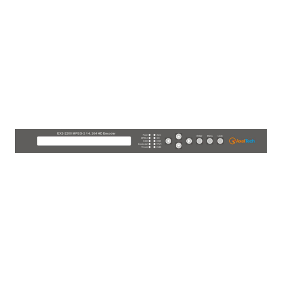
2.4 PRINCIPLE CHART 2.5 APPEARANCE AND DESCRIPTION Front Panel Illustration LCD window Indicators Up and down, left and right navigation buttons Enter button: for confirm Menu button: for back step Lock button: press to lock set Rear Panel Illustration XLR input connectors (for stereo audio 1-2 input) XLR input connectors (for stereo audio 3-4 input) [FOR 5.1 surround input) RCA input connectors (for stereo audio 1-4 input or 5.1 surround input) AES input connector (for only one channel digital stereo) -
Page 6: Installation Guide
L/R: For Mono or Stereo input (Analog) L/R/LS/RS/C/Sub: For 5.1 surround input (Analog) AES: For single digital stereo audio input 3 INSTALLATION GUIDE This section is to explain the cautions the users must know in some case that possible injure may bring to users when it’s used or installed. -
Page 7: Enviromental Requirements
The area of the conduction between grounding wire and device’s frame should be no less than 25 mm. 4 FRONT PANEL OPERATION EX2-2200 front panel is the user operation interface. Through that the user can configure the device manually. The LCD is a 2-line * 40-characters, back-lit, dot-matrix. - Page 8 AN OVERVIEW OF THE LCD MENUS Switch On Initializing General Status Error Type Check 1 Alarm Status 2 System Setting 2.1 Network 4.1 IP Address 4.2 Subnet Mask 4.3 Gateway 4.4 MAC Address 2.2 Reset Web Yes/No 2.3 Output set 2.4.1 Mode 2.4.2 Bit rate 2.4.3 Dest IP...
-
Page 9: Initial Status
4 Video Setting 4.1 Video Port 4.2 Video Bit rate 4.3 Encode Type 4.4 Closed Caption 4.5 PID 4.6 Stream IP 4.7 Chroma Sample 4.8 Aspect Ratio 4.9 Rescaled 4.10 GOP Structure 4.11 GOP Size 4.12 Rate Ctrl Mode 4.13 IDR Frequency 4.14 Sync loss Image 4.15 Coding Mode 4.16 Profile... -
Page 10: General Settings For Main Menu
HD Encoder: to indicate the device name. XX.XX/XX.XX Mbps: to indicate the current encoding Bit Rate and total Output Bit Rate FMT: to indicate source signal resolution format VP/AP: to indicate the Video and Audio Signal source port. ... - Page 11 The MAC is read only on the front MAC Address panel. It is can be modified in the Web 00:11:22:33:55:11 management interface. 4.3.2.2 RESET WEB At this interface, by pressing ENTER again, users can select to reset web or not. The operation interface will turn up as following page: The current mode The current option and...
- Page 12 User can enter 2.4.3 – 2.4.10 respectively to check or modify out IP parameters. Dest IP 224.002.002.002 Dest Port 1234 Source IP 192.168.002.137 Source Port 2007 Dest MAC 01:00:5E:02:02:02 Source MAC is read only on the front Source MAC panel.
-
Page 13: Audio Setting
The audio sample rate is 48 KHz without other options. Audio Sample Rate 48 KHz [48 KHz] 4.3.3.3 AUDIO PAIR EX2-2200 supports 4 stereo (8 mono) or one DD 5.1 (AC3) audios embedded to mix with the video to form a stream output. Audio pair Pair2 [02/06] Pair1... - Page 14 Drop: Audio data is captured. Pair-1: A single (channel 1) audio stream is captured. Pair-2: 2 audio (channel 1&2) streams are captured. Pair-3: 3 audio (channel 1 to 3) streams are captured. Pair-4: 4 audio (channel 1 to 4) streams are captured. 5.1CH: Surround (5.1) for Dobby/AC3 5.1 channel.
- Page 15 Pass Through EX2-220 supports AC3 audio to passthrough from SDI input. User can decide to switch on AC3 Pass through function or not under this menu. Pass Through Yes [01/02] [Yes] Volume User can set the Audio Volume Level under this menu. Audio Volume Level Level 1 [01/04] [Level 1]...
-
Page 16: Video Setting
AAC Profile Select AAC profile among LC, HE and HEV2. AAC Profile [01/03] [LC] HEV2 AAC Version User can set the AAC encoder version under this menu. AAC Version MPEG-2 [01/02] [MPEG-2] MPEG-4 AC3 Destype User can set the AC3 Destype under this menu. AC3 Destype [01/02] [DVB]... - Page 17 Video Port Press ENTER to enter menu Video Port. It displays the current mode of video input. Press ENTER again to enter the setting interface, move the square bracket with LEFT/RIGHT keys to select the target mode and press ENTER to confirm.
- Page 18 Chroma Sample Select one Chroma Sample mode from the 2 options listed. They are applicable for both MPEG2and H.264 encoding mode. Chroma Sample [01/02] [4:2:0] 4:2:2 Aspect Ratio Select aspect ratio mode from option listed. SD Video can choose from 4x3 and 14:9. HD Video only can choose 16:9. Aspect Ratio 16x9 [01/01]...
- Page 19 Sync Loss Image User can choose the image type to encode during loss of video source sync. Sync Loss Image Color [01/02] [Color] Black Coding Mode Choose the coding mode from the options listed. Code Mode Auto [Auto] Frame Field MBAFF ...
-
Page 20: Save Configuration
Video Buffer User can select to turn on/off the video buffer. Video buffer On [01/02] [Off] Source error User can check the source error which is used for encoding. Source error Detect Ignore Resyne Adj Winforamt User can check the source error which is used for encoding. Source error [04/04] Disable buttom Top Frame... -
Page 21: Version
VERSION 4.3.8 User can check the software version and hardware version of this equipment under this submenu. HD Encoder SW: XX.XX HW: XX.X.X 5 WEB NMS Operation User can not only use front panel to set configuration, but also control and set the configuration with a PC (Personal Computer) by connecting the device to web NMS Port. -
Page 22: Operation
5.2 OPERATION System Information When we confirm the login, it displays the SYSTEM INFORMATION interface as Figure-2 where user can view the system information. The system User can click any item here to automatically reads enter the corresponding and displays the interface to check information or current encoding set the parameters. - Page 23 5.1CH: Surround (5.1) for Dobby/AC3 5.1 channel. “Help” Function In “Encode Setting” Interface, whenever the mouse cursor is suspended on one item, a question mark appears by the cursor and the corresponding item comes to hyperlink state (Figure-4). Click the hyperlink item to trigger a text window to give instructions on properly setting the corresponding item.
- Page 24 Parameter -> Video Setting Click “Video Setting” on the top column and it displays interface as Figure-6. User can set the Video parameters. Video Input interface: SDI, HDMI, YPbPr, CVBS optional Encode Type: MPEG-2, H.264 optional CC Setting Output TS Bitrate:This param is read only, and it changed by the Bitrate(Mbps) para which is in the output page...
- Page 25 Parameter -> Output Setting. Click “Output Setting” on the top column and it displays interface as Figure-7. User can set the output parameters by inputting a value or selecting a mode in the pull-down list. Disable: Program stream will not output from IP port, just output from ASI Port.
- Page 26 Advanced->Dolby Metadata Click “Dolby Metadata” on the top column and it displays interface as Figure-9. User can set the dolby AC3 metadata by inputting a value or selecting a mode in the pull-down list. Please pay attention to the “Warning”...
- Page 27 Figure-10 Advanced->SDI Channel Set Click “SDI Channel Set” on the top column and it displays interface as Figure-11. User can set the SDI channel by selecting a value in the pull-down list. Figure-11 Advanced->OSD Settings Click “OSD Settings” on the top column and it displays interface as Figure-12-14. User can insert the logo, caption and QRcode.
- Page 28 Select to configure logo, caption or QRcode Browse and select the Put your logo everywhere Logo which has been created Click here to comfirm the LOGO you selected Figure-12 Caption–Caption insert configuration Put your caption anywhere Click each one of the inserted OSD, then name it and select one “affairs Select the text color and Idx”...
- Page 29 Input your QRcode URL here Browse and select the QRcode which has been created Put your QRcode everywhere Figure-14 Advanced -> OSD affairs settings Click “OSD affairs settings” on the top column and it displays interface as Figure-15 where user can configure the osd affairs as per prompts.
- Page 30 Figure-16 System ->Update Software Click “Update Software” on the top column and it displays interface as Figure-17 where user can update the software for the device. Click browse button to find the update file and click “Update” button to start updating. Browse Button Figure-17 ...
- Page 31 Figure-18 System ->Modify Password Click “Modify Password” on the top column and it displays interface as Figure-19 where user can reset the account information as needed. Figure-19 System ->Network Setting Click “Network Setting” on the top column and it displays interface as Figure-20 where user can check or reset the network.
-
Page 32: Troubleshooting
6 TROUBLESHOOTING DEXIN’s ISO9001 quality assurance system has been approved by CQC organization. For guarantee the products’ quality, reliability and stability. All DEXIN products have been passed the testing and inspection before ship out factory. The testing and inspection scheme already covers all the Optical, Electronic and Mechanical criteria which have been published by DEXIN. -
Page 33: Final Consideration And Axel Technology Contact
8 FINAL CONSIDERATION AND AXEL TECHNOLOGY CONTACT ________________________________________________________________________________________________ ________________________________________________________________________________________________ ________________________________________________________________________________________________ ________________________________________________________________________________________________ ________________________________________________________________________________________________ ________________________________________________________________________________________________ ________________________________________________________________________________________________ ________________________________________________________________________________________________ ________________________________________________________________________________________________ ________________________________________________________________________________________________ ________________________________________________________________________________________________ ________________________________________________________________________________________________ ________________________________________________________________________________________________ ________________________________________________________________________________________________ ________________________________________________________________________________________________ ________________________________________________________________________________________________ ________________________________________________________________________________________________ ________________________________________________________________________________________________ ________________________________________________________________________________________________ ________________________________________________________________________________________________ ________________________________________________________________________________________________ ________________________________________________________________________________________________ ________________________________________________________________________________________________ ________________________________________________________________________________________________ ________________________________________________________________________________________________ ________________________________________________________________________________________________ ________________________________________________________________________________________________ ________________________________________________________________________________________________ ________________________________________________________________________________________________ ________________________________________________________________________________________________ ________________________________________________________________________________________________ ________________________________________________________________________________________________ ________________________________________________________________________________________________ ________________________________________________________________________________________________ ________________________________________________________________________________________________ ________________________________________________________________________________________________...
Need help?
Do you have a question about the EX2-2200 and is the answer not in the manual?
Questions and answers