
Summary of Contents for GAS Gasmaster
- Page 1 Gasmaster 1 to 4 channel gas detection control panel Installation, Operation and Maintenance Manual...
- Page 2 The equipment described in this manual may have mains voltages applied to it. Ensure correct safety procedures are adopted before working on the equipment. The equipment described in this manual is designed for the detection of flammable and/ or toxic gases. Detectors may be sited in hazardous areas. Ensure local safety procedures are adopted before carrying out any maintenance or calibration work.
-
Page 3: Table Of Contents
Installation ..........................3 Please read this first ........................3 Before installation ........................4 General ............................4 Mounting............................5 Cabling requirements ......................5 Installing gas and fire detectors ..................6 Installing output devices ......................6 Connecting mains power ..................... 6 Connecting input devices ....................7 Connecting output devices ....................11 2.10 Applying power ........................13... -
Page 4: Introduction
1. Introduction 1.1 About Gasmaster 1.2 About this manual Gasmaster is a gas and fire control panel, designed The manual is divided into sections which to monitor remote gas and fire detectors. detail procedures for installing, operating and Gasmaster can also monitor flame detectors as maintaining Gasmaster. -
Page 5: Instructions For Use As Part Of An Atex Approved System
1. Introduction 1.3 Instructions for use as part of an ATEX approved system Gasmaster is approved according to the 94/9/EC ATEX Directive when used as part of a system with intrinsically safe gas detectors and I.S. barriers. Gasmaster has been certified according to EN60079- 25:2010 Explosive atmospheres - Intrinsically safe electrical systems. -
Page 6: Installation
Please follow the installation instructions for a pre- 2.9 Connecting output devices configured Gasmaster 4. Additional information 2.9.1 Audible visual alarms on setting-up your Gasmaster system can be found in 2.9.2 Common relay connections section III. Operation. 2.9.3 Channel relay connections Step-by-step instructions 2.9.4 Analogue outputs... -
Page 7: Before Installation
2.2 General This section describes how to get started with a Gasmaster 4 or Gasmaster 1 system that has been pre- configured for the detectors supplied. Figures 2.1, 2.2 and 2.5 show the internal structure of Gasmaster. See the Specification and Inspection Certificate provided with your system for full details of its configuration. -
Page 8: Mounting
2. Installation 2.3 Mounting The Gasmaster power supply contains no user replaceable fuses. All Gasmaster systems should be installed in a safe area. Short circuit protection Consider location, cabling and earthing requirements. Each detector input is short-circuit protected. Self- Figure 2.3 provides a dimensional view of Gasmaster. -
Page 9: Installing Gas And Fire Detectors
2.6 Installing output devices current drawn by that detector is different for each Gasmaster can drive 12 V dc or 24 V dc audible visual device. Please refer to the relevant Installation, alarms directly via the Audible Visual drive terminals Operating and Maintenance Instructions provided on the terminal PCB. -
Page 10: Connecting Input Devices
Inputs can be gas detectors or flame detectors in 4-20 conventional smoke/heat detectors or ESU. mA 2-wire sink, or 3-wire sink or source configurations. Gasmaster will track inputs from 3 to 21.5 mA at which • mV Pellistor module for mV bridge type flammable point an ‘over-range’... - Page 11 Gasmaster provides this monitoring function to ensure Figure 2.9 shows a typical wiring configuration for a a sample is being drawn. Gasmaster provides a 2-wire 24 3-wire detector. Set the link on the 4-20 mA/ Fire input V dc supply to the sampling device. Separate Gasmaster...
- Page 12 2. Installation...
- Page 13 (ESU) inputs Figure 2.13 shows the wiring configuration for Gasmaster has inputs for the connection of remote monitoring the ESU sampling device. Gas detectors switches to inhibit alarm outputs or accept and reset fitted to the ESU should be cabled separately to the alarms.
-
Page 14: Connecting Output Devices
2. Installation may be powered; contact Gas Alarm Systems for Warning advice. Gasmaster is compatible with 12 V dc or 24 V dc Gas Alarm Systems strongly recommends that remote A/V alarms: refer to Figure 2.16 for link settings. inhibit switches be key operated only, and that... - Page 15 110% of range is designated 2.9.3. Channel relay connections by Gasmaster as a fault condition. The signal will be set to 2 mA to indicate when a channel is inhibited, and 0 Gasmaster 4 provides Double-Pole-Change-Over mA when a channel is in fault.
-
Page 16: Applying Power
4.4.) Gasmaster will not power up until an external power supply is applied. Apply power to Gasmaster from either the AC or 24 V dc external supplies. Outputs are inhibited for a preset time after power-up, and the system will perform a start up sequence testing alarm indicators and the internal sounder. -
Page 17: Commissioning
Gasmaster 4 in the dc mV range to test-points TP12 and TP13 on with four mV pellistor flammable gas the Gasmaster mV pellistor input module. Adjust the detectors: 3 hours ‘BALANCE’ potentiometer until the meter reads ‘300 Gasmaster incorporates protection to prevent mV’... - Page 18 Inhibit all channels during the as necessary and press Continue calibration process. 6. When “Apply Gas” is displayed, apply gas to the How to set global inhibit: detector and press Continue , allow readings to From the Supervisor menu, scroll down to Inhibit settle.
- Page 19 Flame detectors require a UV or IR torch (depending on detector type) to simulate alarms. Inhibit the relevant channel, shine the torch at the detector and check that FIRE is shown on the Gasmaster display. For 4-20 mA detectors, also check that the appropriate alarm level is displayed.
-
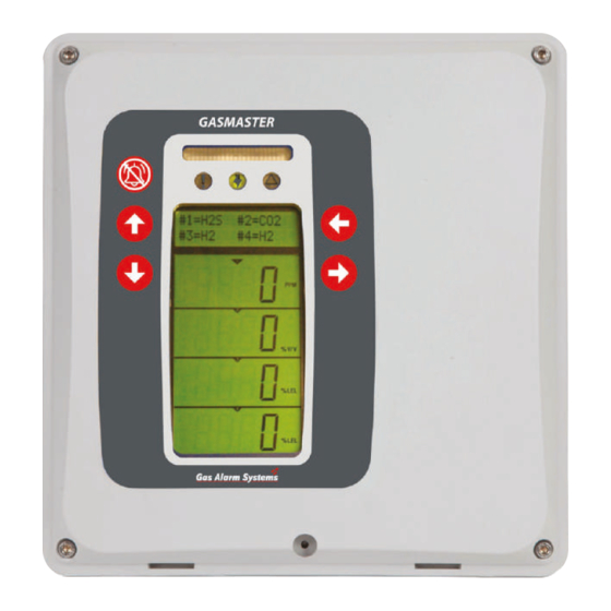
Page 20: Operation
See section 3.8 The Operator Panel allows you to communicate for more information on alarm conditions. with Gasmaster. Use it to monitor the status of all attached field devices, determine system settings and configuration of field devices. Figure 3.1 shows the Operator Panel and typical display under normal, non- alarm monitoring conditions. - Page 21 Display panel LEDs when configuring text or entering the Supervisor password The LEDs on the Gasmaster Display Panel indicate the following: In Supervisor Mode (see section 3.7), use the Up Yellow Fault LED: and Down buttons to change values or settings.
-
Page 22: Gasmaster Start Up Sequence
from the channel display area. Press the Continue 3.2 Gasmaster start up sequence button whilst still in the Menu Contrast screen, use the At power up during Gasmaster installation, or when and Down button to choose Menu Display or Gasmaster is restarted, Gasmaster will initialise the Channel Display. -
Page 23: Using The Menu System
For example, if you were using Supervisor mode When inhibited Gasmaster will: the last time, the menu display will show this: ■ Display the ‘inhibit’ symbol on the channel display for each affected channel. -
Page 24: Using The Control Panel In Supervisor Mode
Note: When the Supervisor mode is active the Warning personnel. A Gasmaster system that has been inhibited LED on the control panel will illuminate without other safety precautions being in place may not provide the protection for which it was designed. -
Page 25: In The Event Of An Alarm
It is advisable to check that no flammable gas The gas reading will cycle back and forth between the remains in the area of the detector before re-setting. -
Page 26: In The Event Of A Fault
33 ‘Channels #1 to #4’ from the Supervisor faults menu. configuration menu. A list of faults can be found in the “Menu system overview” on page 24. 3.11.2. Limitations If Gasmaster is used in a manner not specified in this manual, the protection provided may be impaired. - Page 27 * * #1 denotes the channel number and therefore may read #2, #3 or #4 on Gasmaster. The fault codes are numbered to relate to a particular channel where appropriate (e.g. fault code 19 means there is a...
- Page 28 Menu system overview...
- Page 29 Chan#1 pellistor saver Pellistor saver mode has been disabled, the sensor 41, 42, 43, 44 disabled may be damaged if exposed to gas concentrations above 100%LEL. * #1 denotes the channel number and therefore may read #2, #3 or #4 on Gasmaster.
- Page 30 Indicates the DC supply level from either the Value = 19.8 to 40 V internal PSU or an external DC supply. Configuration See table Supervisor menu : * #1 denotes the channel number and therefore may read #2, #3 or #4 on Gasmaster.
- Page 31 Menu system overview Actions menu (allows basic tests and adjustments) Menu Item Values Description (as shown on display) Audio visual Audio Visual: Drives Audible Visual alarm terminals to test external Test alarm? audible visual alarms Values = Testing beacon Beacon output becomes active for 3 seconds, followed by;...
- Page 32 Use the UP and Down buttons to enter the concentration of the calibration gas (e.g. 50% LEL,10 ppm etc.). Gasmaster will store the gas value entered so that it does not need to be adjusted next time the sensor is calibrated.
- Page 33 Input signal was out of acceptable range, re- Fail calibrate the detector and check that its output current is proportional to the gas level Reminds the user to remove the calibration gas and re-expose the detector to clean air. User action Purge gas Forces common level 1, 2 or Fault relays.
- Page 34 Values Description (as shown on display) Calibrate No alarms will be activated on Gasmaster. Use to test remote displays. Press Back to exit, the input will return to its normal state. Forces level 1, 2 relays for the selected channel.
- Page 35 Menu system overview Supervisor menu (allows system tests to be performed, and configurations to be changed. cont. A password is required to enter this mode, see section 3.7 for details.) Menu Item Values Description (as shown on display) Relay common Alarm L1 common Determines the operation of the common alarm and Type...
- Page 36 8% of full scale, the level of suppression is reduced. Interpret 2mA* Values = Fault Some gas detectors produce a 2 mA signal to indicate a Warning certain state. Inhibit This option determines how Gasmaster interprets a signal between 1 and 3 mA.
- Page 37 A similar menu is available for Level 2 alarm relays, with the exception that the 'Off Threshold' and 'Indication' options are not available. Direction Alarm L2 #1* Threshold Relay type Relay drive * #1 denotes the channel number and therefore may read #2, #3 or #4 on Gasmaster.
-
Page 38: Maintenance
“Warnings menu (lists warnings present on the How to perform Inhibit system)” on page 26. This message can be reset using Gasmaster PC, which also allows the period after which 1. From the normal operating display, press the the message is displayed to be adjusted. -
Page 39: Detector Calibration
Gasmaster PC software at any time. The event log is held in RAM (volatile memory), so in the event of a Replacement batteries should be Yuasa UCEL Y1.2-12, complete power failure all data will be lost. -
Page 40: Adding An Input Module
5. Adding an input module The 4-channel version of Gasmaster may be supplied pre-fitted with between one and four input modules of the following types: • 4-20 mA/Fire module for 4-20 mA type detectors, conventional smoke/heat detectors or ESU. • mV Pellistor module for mV bridge type flammable gas detectors. -
Page 41: Appendix A: Specifications
ATEX EN60079-25:2010 Explosive atmospheres - Intrinsically safe electrical systems. Intrinsically safe electrical systems. Event log access requires Gasmaster PC software and communication port. Event log data is held in non-volatile memory, data will be lost in the event of a complete system power failure. -
Page 42: Appendix B: Spare Parts And Accessories
Communications Kit Includes Gasmaster PC software, connection lead and RS485/232 converter. E07635 Communications port 3-pin connector for fitment to Gasmaster to enable interface with the Communications Kit. Comes complete with wiring loom for connection to the RS-485 terminals. S012303 Front cover assembly for Gasmaster 1... -
Page 43: Appendix C: Display Characters
3.7 to select the required characters. For some string types the available characters may be restricted, only the applicable characters will be shown. For example the detector name (e.g. gas type) is restricted to groups 4 and 7 (numerals and upper case) only:... -
Page 44: Warranty Statement
Warranty Statement This equipment leaves our factory fully tested and Gas Alarm Systems reserves the right to determine a calibrated. If within the warranty period of one reduced warranty period, or decline a warranty period for any sensor supplied for use in an environment or... - Page 45 Unit 4, Halfpenny Close, Knaresborough, North Yorkshire HG5 0TG. Tel: 01423 862240 Fax: 01423 860239 Email: sales@gasalarmsystems.co.uk www.gasalarmsystems.co.uk...
Need help?
Do you have a question about the Gasmaster and is the answer not in the manual?
Questions and answers