
Subscribe to Our Youtube Channel
Summary of Contents for GCS Basyx VAV
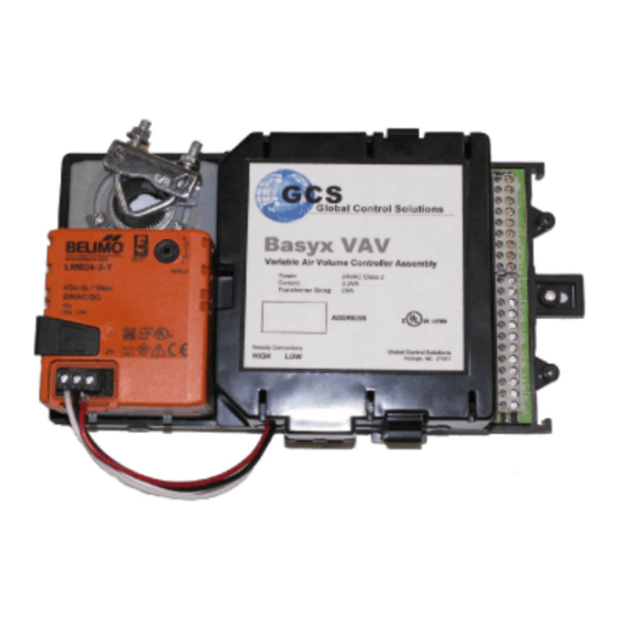
- Page 1 Global Control Solutions Basyx VAV / VVR Variable Air Volume Controller Installation Manual VAV/VVR-IM Revision 3.3 10/07/2020...
-
Page 2: Table Of Contents
BASYX VAV / VVR Variable Air Volume Controller Table of Contents Before Installing VAV Board Layout Mounting the Unit New Construction Retrofit Connecting the Power Communications Bus Wiring Setting The Device Address Connecting Temperature Sensors Room Sensor Duct Sensor Connecting Digital Inputs... -
Page 3: Before Installing
If using the BASYX VVR board with a motor other than a BELIMO, contact your GCS dealer to verify compatibility and power requirements. -
Page 4: Vav Board Layout
VAV / VVR BOARD LAYOUT VELOCITY SENSOR RS485 COMMUNICATION BUS NOT USED ROOM & DUCT TEMPERATURE DIRECT CONNECTION PORT (RJ11 ON ROOM SENSOR) MODULATING REHEAT VALVE (0-10VDC) OPTIONAL 0-10K DAMPER FEEDBACK SETPOINT ADJUSTMENT (SLIDEBAR ON ROOM SENSOR) DIGITAL OUTPUT RELAYS (4 SPST / N.O.) OVERRIDE BUTTON ON ROOM SENSOR DIGITAL INPUT 2 DAMPER ACTUATOR... -
Page 5: Mounting The Unit
MOUNTING THE UNIT VAV NEW CONSTRUCTION INSTALLATION The VAV must be mounted in a relatively clean environment, free from major airborne dust and contaminants (moisture, oil, etc.). Keep the VAV away from high voltage equipment that might disrupt communications and away from high vibration equipment. - Page 6 NEW INSTALLATION CW OPEN DAMPER The VAV assembly operates whereas the Belimo actuator rotates CLOCKWISE to open the damper. To connect the actuator to the damper shaft: Turn the damper to the closed position. Press the black triangular shaped clutch on the right edge of the actuator and rotate the actuator fully counter-clockwise.
- Page 7 VVR RETROFIT INSTALLATION The VVR must be mounted in a relatively clean environment, free from major airborne dust and contaminants (moisture, oil, etc.). Keep the VVR away from high voltage equipment that might disrupt communications and away from high vibration equipment. Do not mount the unit near any sources of electromagnetic interference (EMI) or flammable vapors.
-
Page 8: Retrofit
RETROFIT CW OPEN DAMPER The VVR default logic operates whereas the board activates the CCW board output to open the damper. To connect the actuator to the damper shaft to open in a CLOCKWISE rotation: Make sure the damper is closed, and the existing actuator is in the full counter-clockwise position. - Page 9 RETROFIT CCW OPEN DAMPER If the VVR is installed on a box which requires that the damper rotates COUNTER-CLOCKWISE to open, connect as follows: Make sure the damper is closed, and the existing actuator is in the full clockwise position. Connect the existing 3-wire floating actuator with 2-pair cable as shown in Figure 7.
-
Page 10: Connecting The Power
VAV/VVR BOARD PER VAV/VVR FOR TRANSFORMER SIZING. 24VAC THE VAV/VVR MAY BE POWERED FROM THE EXISTING CONTROL TRANSFORMER 24VAC TRANSFORMER IN A FAN POWERED OR REHEAT BOX IF AVAILABLE. 120VAC CIRCUIT Figure 8: BASYX VAV / VVR power connections Page 10... -
Page 11: Communications Bus Wiring
COMMUNICATIONS BUS WIRING The BASYX VAV / VVR can be used in a stand alone configuration with a wall mounted sensor, with a PSC in smaller applications, or in an array utilizing hundreds of units. When used in an application smaller than 32 total units, a minimum of one (1) PSC must be installed. - Page 12 COMPLEX COMMUNICATIONS BUS WITH EXPANDER MODULES BASYX SCM SUPERVISOR MAIN RS485 COMMUNICATIONS BUS UP TO 32 TOTAL UBE CONTROLLERS B ASYX SC E BASYX UBE EXPANDERS CHANNEL RS485 COMMUNICATIONS BUS BASYX VAV/VVR CONTROLLERS VAV 1-1 VVR 2-1 VAV 3-1 VVR 4-1 VAV 1-2 VVR 2-2...
-
Page 13: Setting The Device Address
If more than one VAV / VVR is used on the same communications bus then each device must have a different address for proper communication. Removing the clam shell cover from the BASYX VAV assembly will expose the dip switch which sets the individual controller address. Refer to Appendix 1 for setting the device address to a number between 1 and 64. -
Page 14: Connecting Temperature Sensors
CONNECTING THE TEMPERATURE SENSORS The BASYX VAV / VVR provides predetermined analog and digital inputs for variable air volume terminal control. Please refer to the TYPICAL VAV INSTALLATION DRAWING at the end of this document for details on complete wiring of the VAV / VVR controller inputs and outputs. -
Page 15: Room Sensor
CONNECTING THE ROOM SENSOR The room sensor monitors the space ambient temperature, as well as optional setpoint adjustment and system override function. In addition, the sensor can be provided with an RJ11 jack, which allows connection to the individual controller with a laptop through the room sensor. Mount the room sensor according to the manufacturer’s instructions. -
Page 16: Duct Sensor
CONNECTING THE DUCT SENSOR The duct sensor monitors the incoming supply air temperature, and allows the reverse operation of the damper upon a high entering duct temperature. This is typically used on air handling equipment with morning warmup function. The reversing function will reverse the operation of the damper i.e. open on a call for heat. Mount the sensor upstream from the VAV box in the branch duct according to the manufacturer’s installation instructions. -
Page 17: Connecting Digital Outputs
CONNECTING THE DIGITAL OUTPUTS The VAV / VVR provides four (4) SPST relay outputs for control of box fans and/or electric heat strips. The outputs provide a normally open contact, and will interface with most box manufacturer control sequences. Figure 13 shows output wiring utilizing external pilot relays. -
Page 18: Fan Powered Box Outputs
Figure 14 shows typical wiring of a fan-powered reheat box which uses the 24VAC transformer in the VAV box controls to power the VAV / VVR board. This is a typical view, and the box manufacturer instructions should be referenced for exact wiring details. BOX TERMINAL STRIP Figure 14: Typical Fan-Powered Box Output Wiring INSTALLING THE VARISTORS... -
Page 19: Connecting Analog Output
CONNECTING THE ANALOG OUTPUT One 0-10vdc analog device may be controlled by the VAV / VVR, and is used to control hot water reheat or baseboard heating valves. Figure 16 illustrates typical device connections. When connecting the actuator, make sure to be consistent with L1 (HOT) and L2 (COMMON) connections within the system. BELIMO or OTHER ACTUATOR IMPORTANT !! WHEN POWERING THE ACTUATOR... -
Page 20: Connecting The Velocity Sensor
CONNECTING THE VELOCITY SENSOR The VAV / VVR uses an on-board differential pressure sensor for monitoring of air flow and velocity of the box discharge to the conditioned space. On the VAV, the sensor is connected with flexible tubing to external taps on the lower edge of the enclosure marked “HIGH”... -
Page 21: Operation
OPERATION The red indicator light next to the 24VAC terminal block illuminates solid when the power is on. When the unit is operating properly, the two (2) CPU lights will blink intermittently to indicate proper CPU operation. BASIC TROUBLESHOOTING If the VAV / VVR does not operate properly, perform the necessary troubleshooting as described below. SYMPTOM ACTION Failure to communicate:... -
Page 22: Specifications
SPECIFICATIONS Communication: EIA RS-485 at 9600 baud on 22AWG shielded, plenum rated cable (recommended Belden 6500FE or equivalent) Power Requirements: 24VAC (-10% / 5%), 50/60/Hz 3.2VA for VAV 2.4VA plus actuator current for VVR Recommend 5VA transformer sizing for AC power Analog Inputs: (3) 10K ohm thermistor Type II. -
Page 23: About The Basyx Product Line
ABOUT THE BASYX PRODUCT LINE The VAV / VVR is one product in a line of BASYX control products. The TriComm interface software package is a Windows based human interface used with the BASYX automation and control system. Tricomm will operate on any personal computer with the Windows 98,ME,NT,2000 or XP, Vista or Windows 7 operating system. -
Page 24: Appendix 1: Basyx Address Switch Settings
APPENDIX 1 - BASYX ADDRESS SWITCH SETTINGS ADDRESSES 1-32 ADDRESS SW 1 SW 2 SW 3 SW 4 SW 5 SW 6 SW 7 SW 8 Page 24... - Page 25 ADDRESSES 33-64: ADDRESS SW 1 SW 2 SW 3 SW 4 SW 5 SW 6 SW 7 SW 8 Page 25...
-
Page 26: Appendix 2: Manufacturer Box Constants
APPENDIX 2 - MANUFACTURER BOX CONSTANTS The following tables show flow calculation constants for the most commonly used manufacturers of variable air volume terminals. Manufacturers Listed: Carnes Company Environmental Technologies, Inc. (ETI) Krueger Metal Industries Price Industries Redd-I Trane Company Temperature Industries Titus Tuttle &... - Page 27 ENVIRONMENTAL TECHNOLOGIES Box Type & Model Inlet Size (in.) CFM @ 1" Area K (Box Constant) 4" Round 0.079 1.628 Models: SDR / CFR / VFR 5" Round 0.126 1.657 6" Round 0.184 2.896 Newer style as of 10/92 8" Round 0.333 2.515 10"...
- Page 28 METAL INDUSTRIES Box Type & Model Inlet Size (in.) CFM @ 1" Area K (Box Constant) All models: 400th Series 6" Round 0.20 1.91 8" Round 0.35 2.10 10" Round 1540 0.53 1.89 90 deg travel, either direction to close 12"...
- Page 29 TRANE COMPANY Box Type & Model Inlet Size (in.) CFM @ 1" Area K (Box Constant) 4" Round 0.14 3.27 Single Duct: VCCD / ED / WD / VSSD / VCCE 6" Round 0.20 2.65 WE / EE 8" Round 0.35 2.44 10"...
- Page 30 TUTTLE & BAILEY Box Type & Model Inlet Size (in.) CFM @ 1" Area K (Box Constant) 4" Round 0.090 2.97 All Models: SDV / FPC / FPV / HPV / DDV / 5" Round 0.136 2.99 6" Round 0.196 2.89 7"...
- Page 31 DAMPER ONLY INSTALLATIONS In-Line Dampers or Boxes Without Flow Ring Box Type & Model Inlet Size (in.) CFM @ 1" Area K (SSE Sensor) 4" Round 0.09 1.00 In-Line Round Damper 5" Round 0.14 1.00 6" Round 0.20 1.00 Boxes without Flow Ring 7"...
-
Page 32: Appendix 3: Recommended Cable
This document lists the recommended cable types and part numbers for the various connections to the BASYX building automation and control system hardware. GCS recommends the New Generation product line from Belden Wire & Cable, and suggests that any substitutions meet or exceed the technical specifications of those cables listed. - Page 33 avoided due to capacitance issues. ALL cables should be shielded type, and drain wires should be connected to solid earth ground. Page 33...
Need help?
Do you have a question about the Basyx VAV and is the answer not in the manual?
Questions and answers